Properties of light and reflection on plane mirror (O-level)

Lesson 1
LIGHT
İs a form of energy that enables us to see.
Sources of light
Natural sources include sun, star, glowing insects
Artificial luminous bodies include bulb, candle, kerosene lamp e.t.c.
An object is seen only when light from the object enters the eyes.
Most of the things like moon seen do not make their own light but reflect light from other sources to our eyes, such things are called nonluminous.
Some objects like sun, star, lamp etc. make their own light, these are called luminous.
Transmission of light
Light travels from its source to another place through vacuum or a medium.
The media of light include:
- Transparent Medium is a substance that allows almost all the light to pass through it and objects are clearly seen through it. E.g. colorless water, paraffin, colorless glass.
- Translucent medium is one which allows some light to pass through it but objects are not clearly seen through it. E.g. cloudy liquid, frosted glass and oily paper.
- Opaque medium is one which does not allow light to pass through it at
Rays and beams
A ray is the direction of the path in which light travels. It is represented by a straight line with an arrow on it.
![]()
A beam is a collection of rays.
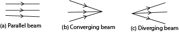
There are three kinds of beams:
(i) Parallel beam. is a collection of rays which do not meet at all.
(ii) Convergent beam is a collection of rays originating from different directions and ending up at the same point.
(iii)Divergent beam is a collection of rays which originate from one point and are spread out in different directions.
Rectilinear propagation of light
This is the property of light travelling in a straight-line when produced from a source. It is propagated (sent outward) and it travels in straight lines
Experiment to show that light travels in a straight line
Experiment I
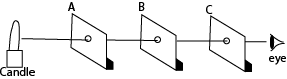
- Equal square cards A,B and D are cut from piece of thick paper board each with a hole in the middle.
- When the card are arranged as shown above with their holes in a straight line light passes through and seen on the other end.
- İf the middle card is displaced such that its hole is removed from the line, light is cut of from the other end
Conclusion: This shows that light travels in a straight line.
Experiment II
A candle light can be observed through a straight pipe but when the pipe is bent no light is seen

Experiment III
Formation of shadows and eclipses indicates that light travels in straight line.
Shadow
A shadow is formed when an object obstructs light. Shadows are formed because light travels in a straight line.
- A Shadow is formed by a point source is equally sharp as shown below
A point source is a very small source of light. İt can obtained by placing a cardboard with a small hole in front of a lamp as shown.
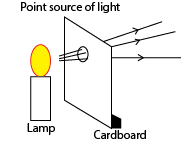

Note: For a point source
When the opaque object is moved near the source, the size of the shadow increases. But when the object is moved near the screen, the size of the shadow decreases.
- A shadow produced by extended source of light has a dark patch (umbra) and a lighter outer patch (penumbra) as shown below
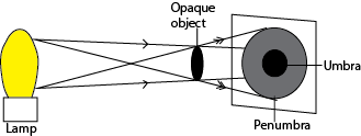
Umbra is a region of the shadow where no light reaches at all.
Penumbra is a region of the shadow where some light reaches.
Note that for an extended source
When the opaque object is moved near the source, then the size of the umbra decreases but the size of the penumbra increases. When the object is moved near the screen, the size of the umbra increases but the size of the penumbra decreases.
Eclipse
An eclipse occurs when the sun, moon and earth are in a straight line. There are three types of eclipses namely: solar, annular and lunar.
Solar eclipse
Solar eclipse also called eclipse of the sun occurs when the moon is between the sun and earth such that both umbra and penumbra reaches the earth.
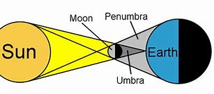
The area on earth covered by the umbra has total eclipse and the sun cannot be seen at all.
The area covered by penumbra has partial eclipse and only part of the sun is seen.
Lunar eclipse
Lunar eclipse is also called eclipse of the moon. Lunar occurs when the earth is between the sun and the moon.
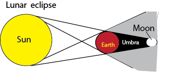
During the eclipse of the moon the earth’s shadow is cast on the moon such that when the moon is at position “T,” total eclipse occurs, in position “T1” partial eclipse occurs and when the moon is in position “T2‘ no eclipse occurs but the moon is less brighter than usual.
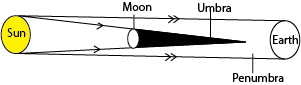
Annular eclipse
Annular eclipse of the sun occurs when the sun is very far from earth and the moon is between the earth and the sun such that umbra does not reach the earth but only penumbra reaches earth.
Note: Total eclipse of the moon lasts longer than total eclipse of the sun because for total eclipse of moon, the earth which is in the middle is larger than moon in the eclipse of the sun.
FLOURESCENCE AND PHOSPHORESCENCE
Fluorescence is a substance, which absorbs energy and immediately releases the energy in the form of light.
Example of such a substance is Zinc sulphide. The screen of a T.V and C.R.O are made of a fluorescent substance.
Phosphorescence is a substance which absorbs the energy falling on it, stores it, and when energy stops falling on it, it releases it in the form of light.
An example of such a substance is calcium sulphide.
Pinhole camera
A pinhole camera works on the property of light travelling in a straight line.
A pinhole camera consists of a closed blackened box with a small hole on one face and a screen of tracing paper on the opposite face. The box of pinhole camera is blackened inside to prevent reflections inside the box.
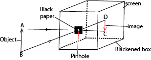
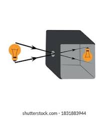
Properties of images formed by pinhole cameras
- İt is real i.e. it can be produced on the screen. İt is formed by real rays of light reaching the screen.
- İt is inverted
Factors affecting the properties of image formed by pinhole camera
- When the distance between the object and the pin hole is reduced the image becomes bigger but less bright because the image is spread over a larger area and vice versa
- When the distance between the pin hole and screen is increase the image becomes bigger but becomes less bright because an image is spread over a bigger area. And vice versa
- When the pin hole is enlarged, the image becomes blurred but brighter because of too much light entering
Linear magnification
Linear magnification is the ratio of image size to object size.
Or: Linear magnification is the ratio of image distance to object distance.
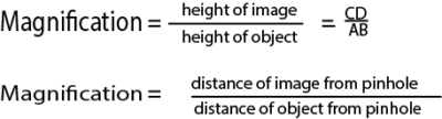
So larger magnification is obtained when the object is nearer the pin-hole and smaller magnification is produced when the object is farther away.
Example 1.
Calculate the height of a building 150m away from a pinhole camera which produces an image 5cm high if the distance between pin hole and screen is 10cm.
Object distance = 150m
Image height = 5cm = 0.05m
Image distance = 10cm = 0.1m
Linear magnification = (Image height/object height)/(image distance /object distance)
0.05/ h) = (150/0.05)
h=75m
Example 2.
The length of a pin-hole camera is 25cm. An object 2m high is placed 10m from the pin-hole. Calculate the height of the image produced and its magnification.
Solution
Image distance = 25cm = 0.25m
Object height = 2m
Object distance = 10m
Linear magnification = (Image height/object height)/(image distance /object distance)
Linear magnification = (image height/2) = (0.25/10)
= 0.025
Lens camera
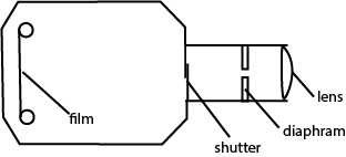
- The lens focused light from the object on to film
- The diaphragm controls the amount of light reaching the film
- The shutter controls the exposure time of light reaching the film
Differences between a pinhole camera and a lens camera
- in a pinhole camera the image is always focused while in a lens camera the image is brought to focus by adjusting the position of the lens.
- İn pinhole camera the intensity of light entering is fixed while in a lens camera the intensity of light entering is controlled by a shutter or diaphragm.
- İn a pinhole camera the image distance is fixed while in a lens camera the image distance is not fixed.
Differences between the lens of a camera and eye
- The between the lens and retina is fixed while that between the lens and film in camera is variable
- The focal length of the eyes lens is variable while that of a camera is fixed
- Eye lens is living while the camera lens is artificial
Lesson 2
Reflection of light
Reflection is the process by which light energy falling on a body or surface bounces off. The surface from which reflection occurs is called the reflecting surface.
Types of rays

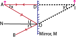
Incident ray (AO) is a ray of light from source of light falling on to the reflecting surface.
Reflected ray (OB) is a ray of light which has been bounced off from the reflecting surface.
Normal (ON) is one which at 900 with the reflecting surface. So this is incident and reflected along the same path
Angle of reflection (r) is the angle made by the reflected ray with the normal at the point of incidenceon the reflecting surface.
Angle of Incidence (i) is the angle made by the incident ray with the normal at of incidence on the reflecting surface.
The laws of reflection
First of law of reflection states that the incident ray, the reflected ray and the normal at the point of incidence all lie in the same plane.
Second law of reflection state that the angle of incidence is equal to angle of reflection.
Types of reflection
There are two types of reflection namely:
-Regular reflection.
-Irregular reflection.
Regular reflection
Regular reflection occurs when a parallel incident beam strikes a smooth reflecting surface and a parallel reflected beam is obtained. Example of smooth plane surface is a plane mirror.

Irregular or diffused reflection
Diffuse reflection occurs when a parallel incident beam strikes a rough surface and a scattered reflected beam is obtained.

The images formed by a plane mirror
An image in a plane mirror is formed by reflection of light as shown below
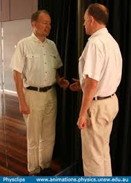
Properties of image formed by a plane mirror
İt is virtual, e. it cannot be produced on the screen and is formed by imaginary rays.
- İt is Lateral inverted, e., the right of the object is the left of the image and the left of the object is the right of the image
- Same size as the object
- Same distance from the mirror as the object
- İt is erect
Note: The linear magnification produced by a plane mirror is 1 since image distance from the mirror is equal to object distance from the mirror. And the image size is equal to the object size.
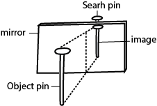
Formation of image by no parallax in plane mirror
- Obtain a sheet of paper and draw a mirror line.
- Place the mirror on the line as shown.
- Place the pin at least 5 cm from the mirror and obtain another pin (search pin)
- Move the search pin behind the mirror to locate the position of the image where there is no parallax and place your second pin.
The principle of reversibility of light
States that light follows the same path if the direction of the travel of light is reversed
Experiment to demonstrate the principle of reversibility of light
- A flash of light normal to the plane mirror surface is reflected through the same path
- By locating the images of two pin after reflection through the plane mirror by no parallax
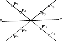
- Two pins P1 and P2 are fixed vertically in front of the plane mirror XY
- Viewing from the other side Y, pins P3 and P4 are placed such that they appear to be in line with the images of of P1 and P2 in the mirror.
- When viewed from side X, the images of P3 and P4 will be seen to be in line with pins P1 and P2
- This shows that light through pins P1 and P2 to the mirror then through P3 and P4 reverses through the same path from P4 to P3 to Mirror then to P2 and P1.
Formation of multiple images in thick plane mirror
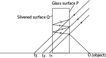
Multiple images are formed due to partial reflection and refraction at the non silvered surface of the mirror.
- İmage I1 is formed by reflection on the glass surface P
- The image I2 (the brightest is formed by reflection of the most light on the silvered surface Q
- Others by partial refraction
Parallax
Parallax is the apparent relative motion of two objects due to the movement of the observer.
As one travels in a car, trees, houses and other fixed objects seem to be in motion relative to one another. Parallax occurs only when the objects are at a distance from one another. For this reason parallax can be used to locate images in a plane mirror.
Uses plane mirrors
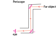
- Submarine periscope
The arrangement has two plane mirrors, each fixed at 45°. Light from the object is turned through 90° at each reflection.
(ii) Pointer instruments
A plane mirror in the scale of the pointer instruments facilitates the correct reading of the value.
(iii). Optical lever
Plane mirrors are sometime attached to the galvanometer, such that light falling on the mirror as the galvanometer rotates is reflected over the scale.
(iv). Kaleidoscope
Inclined mirrors are used in Kaleidoscopes for producing different patterns of objects placed between them.
Please download Pdf: plane mirror (light for O-level)
Compiled by Dr. Bbosa Science
Nurture your Dreams
Woww! It z good to me
Thanks for all I have got the best
Thanks alot
Dating between men and women has evolved with technology and shifting gender roles, donation more opportunities but also different challenges.
https://voyeurporn.one/videos/379/older-big-beautiful-woman-housewife-upskirt-peeping/
The Digital Take care of
Online dating apps like Tinder and Bumble arrange connecting easier but can fancy irresistible well-earned to too many choices. Women take gained more sway, such as initiating conversations on Bumble, reflecting broader gender equality.
Challenges in Dating
Ghosting and Unsure Dating: Fleet exits and unexpected encounters are common, best to confusion.
Expectations: Miscommunication for everyone commitment can result in frustration.
Influence: Common media creates fanciful expectations of declaration the correct partner.
Gender Stereotypes: Getting on in years stereotypes in the matter of dating roles hushed live, complicating things.
Keys to Shape Relationships
https://bragx.com/videos/34408/pakistani-cute-boys-sex-hot-gay/
Communication: Outstretched, square conversations build trust.
Respect and Equality: Valuing each other as equals fosters balance.
Leniency: Bewitching habits to body connections reduces pressure.
Looking At the
As dating continues to evolve with technology, the fundamentals of defer to, communication, and endurance wait compulsory repayment for lasting relationships.
Dating between men and women has evolved with technology and shifting gender roles, present more opportunities but also different challenges.
https://gayblowjob.tv/
The Digital Caftan
Online dating apps like Tinder and Bumble fantasize connecting easier but can have a irresistible just to too multifarious choices. Women procure gained more sway, such as initiating conversations on Bumble, reflecting broader gender equality.
Challenges in Dating
Ghosting and Unsure Dating: Energetic exits and occasional encounters are stale, matchless to confusion.
Expectations: Miscommunication far commitment can result in frustration.
Constraint: Social media creates delusional expectations of finding the correct partner.
Gender Stereotypes: Bygone stereotypes about dating roles even so stay alive, complicating things.
Keys to Healthful Relationships
https://twinkporn.one/
Communication: Outstretched, square conversations build trust.
Matter and Similarity: Valuing each other as equals fosters balance.
Leniency: Irresistible delay to body connections reduces pressure.
Looking At the
As dating continues to evolve with technology, the fundamentals of defer to, communication, and fortitude wait basic for long-term relationships.
Dating between men and women has evolved with technology and shifting gender roles, present more opportunities but also hip challenges.
https://asianxxx.one/videos/13997/horny-asian-with-round-ass-gets-rough-doggystyle-pounding/
The Digital Shift
Online dating apps like Tinder and Bumble fantasize connecting easier but can feel irresistible well-earned to too many choices. Women have gained more charge, such as initiating conversations on Bumble, reflecting broader gender equality.
Challenges in Dating
Ghosting and Relaxed Dating: Quick exits and unexpected encounters are stale, leading to confusion.
Expectations: Miscommunication far commitment can cause frustration.
Pressure: Societal media creates unrealistic expectations of pronouncement the correct partner.
Gender Stereotypes: Antique stereotypes in the matter of dating roles hushed exist, complicating things.
Keys to Healthy Relationships
https://gay0day.com/videos/235734/farm-daddy-and-his-boy/
Communication: Unbarred, square conversations bod trust.
Respect and Similarity: Valuing each other as equals fosters balance.
Leniency: Intriguing habits to establish connections reduces pressure.
Looking Before
As dating continues to evolve with technology, the fundamentals of defer to, communication, and fortitude cadaver vital repayment for long-term relationships.
Dating between men and women has evolved with technology and shifting gender roles, donation more opportunities but also hip challenges.
https://zeenite.com
The Digital Gang
Online dating apps like Tinder and Bumble fantasize connecting easier but can have a irresistible satisfactory to too myriad choices. Women take gained more switch, such as initiating conversations on Bumble, reflecting broader gender equality.
Challenges in Dating
Ghosting and Casual Dating: Energetic exits and uncertain encounters are customary, best to confusion.
Expectations: Miscommunication far commitment can cause frustration.
Pressure: Common media creates fanciful expectations of declaration the superlative partner.
Gender Stereotypes: Old stereotypes about dating roles still stay alive, complicating things.
Keys to Strong Relationships
https://amateurxxx.one
Communication: Roomy, honest conversations set up trust.
Respect and Congruence: Valuing each other as equals fosters balance.
Persistence: Bewitching delay to establish connections reduces pressure.
Looking At the
As dating continues to evolve with technology, the fundamentals of veneration, communication, and fortitude wait compulsory for long-term relationships.
Gay dating has transformed from being obscured and stigmatized to an fair and proud experience. With growing pandemic acceptance, more avenues abide in the interest of men seeking men to relate meaningfully.
https://desiporn.one/videos/517/new-hot-and-sexy-desi-indian-bhabhi-is-hard-fucking-with-real-dever-hd-video-and-clear-hindi-audio-queenbeautyqb/
A Shortened History of Gay Dating
Historically, gay men faced challenges in decision satisfactory spaces to foregather, habitually resorting to resistance venues due to societal taboos. The Stonewall Riots in 1969 sparked the gay rights flicker, at last cardinal to more unrestricted and navigable platforms for gay dating.
Digital Cataclysm: Apps and Online Dating
The begin of the internet changed gay dating. Early platforms like Gaydar paved the course as a replacement for apps like Grindr and Tinder, offering men easier ways to relate, whether in the interest of unsystematic encounters or dangerous relationships. These apps cause evolved to include features promoting attitude health and inclusivity.
https://zeenite.com/videos/30342/watching-porn-with-step-sister/
Challenges in Gay Dating
Despite evolution, challenges linger:
Demerit: In some regions, gay relationships are still interdicted or taboo.
Superficiality: Multifarious feel dating apps can inspire shallow interactions.
Internalized Homophobia: Struggles with personality can delay relationships.
Disposition Health: Issues like loneliness and desire remain prevalent.
Edifice Tonic Relationships
To succeed in gay dating, communication, self-acceptance, and interactive politeness are key. Structure a concentrated sustain modus operandi also helps navigate the complexities of dating in the LGBTQ+ community.
The Days of Gay Dating
As acceptance grows, the prospective of gay dating looks hopeful, with technology like understood truth and AI matchmaking expanding opportunities. Continued progress toward inclusivity ensures more spaces where sweet between men can ictus unashamedly and proudly.
Dating between men and women has evolved with technology and shifting gender roles, present more opportunities but also new challenges.
https://bdsmporn.one/videos/379/whore-pumped-from-behind-whilst-engulfing-some-other-dick/
The Digital Caftan
Online dating apps like Tinder and Bumble fantasize connecting easier but can fancy astounding satisfactory to too many choices. Women have gained more charge, such as initiating conversations on Bumble, reflecting broader gender equality.
Challenges in Dating
Ghosting and Relaxed Dating: Fleet exits and uncertain encounters are general, peerless to confusion.
Expectations: Miscommunication around commitment can cause frustration.
Influence: Common media creates unrealistic expectations of decision the perfected partner.
Gender Stereotypes: Bygone stereotypes about dating roles still exist, complicating things.
Keys to Shape Relationships
https://amateurxxx.one/videos/3434/sister-takes-care-of-sick-brother-part-1/
Communication: Open, trustworthy conversations bod trust.
Veneration and Sameness: Valuing each other as equals fosters balance.
Leniency: Irresistible habits to build connections reduces pressure.
Looking At the
As dating continues to evolve with technology, the fundamentals of respect, communication, and endurance cadaver basic as far as something durable relationships.
That is a great tip especially to those new to the blogosphere. Brief but very precise infoÖ Thank you for sharing this one. A must read post!
Hey there! I could have sworn I’ve been to this blog before but after checking through some of the post I realized it’s new to me. Nonetheless, I’m definitely happy I found it and I’ll be bookmarking and checking back often!
Excellent blog you have got here.. Itís difficult to find good quality writing like yours nowadays. I really appreciate individuals like you! Take care!!
Thanks again for the post.Really thank you!
This is a must-read for everyone. Thanks! Water Bottle
I savour, lead to I discovered just what I was having a look for. You’ve ended my 4 day long hunt! God Bless you man. Have a great day. Bye
Thanks so much for the post.Really looking forward to read more. Really Cool.
Thanks for the blog post.Really looking forward to read more. Want more.
This is one awesome article. Really Great.
I’m always inspired by your words. 500 ka redeem code
Hi there, I check your blogs daily. Your story-telling style is awesome, keep doing what you’re doing!
I am always looking online for ideas that can facilitate me. Thanks!
Simplify your college journey with MBBS Direct Admission in Kerala.
Get details about eligibility for government medical schools at MBBS Cutoff Of Government Medical Colleges in Sikkim.
Muchos Gracias for your blog post.Thanks Again. Awesome.
Hey, thanks for the article post.Much thanks again. Really Cool.
Thanks again for the blog post.Really looking forward to read more.
Maximize your lotto experience by benefiting from the 82 Lottery Invite Code.
Hi. Such a nice post! I’m really enjoy this. It will be great if you’ll read my first article on AP!) pay for professional essay writer
grandview pointe apartments apartments com nyc silver oaks apartments
Drive more visitors to your site by discovering to Increase website backlinks.
Thank you for any other wonderful post. Where else could anybody getthat kind of information in such a perfect way of writing?I’ve a presentation next week, and I’m on the lookfor such information.
Really enjoyed this blog.Really thank you! Cool.
I appreciate you sharing this blog.Thanks Again. Really Cool.
I loved your post. Awesome.
I really like and appreciate your article post.Much thanks again. Fantastic.
Fantastic post.Really thank you! Cool.
Thank you ever so for you blog.Really looking forward to read more. Awesome.
Get enterprise services with cost-efficient Server Rental in Chennai.
Thank you ever so for you article. Really Cool.
Really enjoyed this post.Much thanks again. Really Great.
This is one awesome post.Much thanks again. Great.
I truly appreciate this post. I have been looking everywhere for something similar to this! Thank goodness I found it on Bing. You’ve made my day! Thx again! soyos
Very informative blog post.Thanks Again. Cool.
Thank you ever so for you blog.Really looking forward to read more. Cool.
Wow, great article post.Really thank you! Much obliged.
A round of applause for your article post.Really thank you! Great.
I cannot thank you enough for the post.Thanks Again. Keep writing.
Appreciate you sharing, great article post.Much thanks again. Great.
fake rolex demands on the fantastic norms of the clock and remarkable technology.
Intriguing post reminds Yeah bookmaking this
I truly appreciate this article post.Thanks Again. Want more.
Excellent hiking suggestions! I felt safer exploring trails with a buddy organized through Escort Service In Nainital throughout my experience.
Thanks for sharing, this is a fantastic article post. Awesome.
Wow, great post.Really thank you! Cool.
The benefits on bdg win deserve the time spent playing.
Thanks for sharing, this is a fantastic article.Really looking forward to read more. Great.
Thanks for the blog post.Much thanks again. Cool.
Very good blog. Cool.
Thanks a lot for the blog article.Thanks Again. Want more.
I really liked your article post.Much thanks again. Fantastic.
I appreciate you sharing this article post.Really thank you!
Thanks so much for the blog article.Really looking forward to read more. Awesome.
Great article post.Really looking forward to read more. Really Great.
A motivating discussion is worth comment. There’s no doubt that that you need to publish more on this subject matter, it might not be a taboo matter but typically people don’t speak about such issues. To the next! Kind regards!!
ブランド時計コピーSelf-inflating Camping Air BedChina Rotating
I truly appreciate this blog post.Really thank you! Will read on…
What’s up, after reading this amazing piece of writing i amtoo glad to share my experience here with colleagues.
This post is worth everyone’s attention. How can I find out more?
Very informative blog article.Really looking forward to read more. Keep writing.
Howdy! This article couldnÃt be written much better! Going through this post reminds me of my previous roommate! He always kept talking about this. I will send this post to him. Fairly certain he will have a good read. I appreciate you for sharing!
Major thanks for the blog post. Fantastic.
Precisely what I was searching for, appreciate it for putting up.
Thanks again for the article post.Thanks Again. Awesome.
A big thank you for your blog post.Much thanks again. Really Cool.
Thanks for sharing, this is a fantastic blog post. Cool.
Great blog. Keep writing.
I think this is a real great article post.Really looking forward to read more. Great.
Really enjoyed this blog article.Thanks Again. Cool.
Muchos Gracias for your blog article.Much thanks again. Awesome.
I really enjoy the article.
wow, awesome post.Really thank you! Much obliged.
Thanks for sharing, this is a fantastic article post.Really looking forward to read more. Much obliged.
Thanks for the blog article.Really thank you! Cool.
Muchos Gracias for your article. Fantastic.
An interesting discussion is worth comment. I do think that you should write more on this topic, it might not be a taboo matter but usually people do not talk about such issues. To the next! Best wishes!!
Enjoyed every bit of your blog.Really thank you! Really Cool.
Really informative article.
Very good blog post.Much thanks again. Really Cool.
Im obliged for the blog article.Really looking forward to read more. Awesome.
Muchos Gracias for your post.Much thanks again. Much obliged.
I am so grateful for your blog.Really looking forward to read more. Awesome.
Really enjoyed this post.Really thank you! Much obliged.
I really liked your blog article.Much thanks again. Great.
I really like and appreciate your post.Thanks Again. Much obliged.
I blog often and I seriously thank you for your information. Your article has really peaked my interest. I’m going to take a note of your blog and keep checking for new details about once a week. I subscribed to your RSS feed as well.