Magnetism (A-level revision questions with answers)

1. (a)(i) Write down an expression for the force on a charge, q coulombs moving with velocity, u, at an angle, α, to a uniform magnetic field of flux density B.(01mark)
F = Bqusinα
(ii) Use the expression in (a)(i), to deduce the force on a conductor carrying a current in magnetic field. (03marks)
Using F = Bqusinα
q = It
=> F= BItusinα
Where t is the time and I the current flowing
Since tu = L, the length of a conductor
Then, F = BILsinα
(b) Figure below shows an aluminium bar AB resting on two horizontal aluminium rails connected to a battery through switch K. a magnetic field of flux density 0.10T acts perpendicularly into paper.
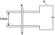
(i) Explain what happens to AB when switch K is closed(03marks)
Current flows in the bar in the direction BA. From the Fleming’s left hand rule, the bar BA will experience a magnetic force and it will move towards the right.
(ii) Calculate the angle to horizontal to which the rail must be tilted to keep AB stationary if its mass is 5.og, current in it is 4.0A and the direction of the field remains unchanged. (04marks)

(c)(i) With the aid of a labelled diagram, describe the structure and mode of operation of a moving coil galvanometer. (06marks)
Drawing

Structure
- It consist of a rectangular coil of fine insulated copper wire wound on an aluminium frame to provide electromagnetic damping.
- The coil together with the frame of aluminium are mounted over a soft iron cylindrical core and freely pivoted on jeweled bearing to minimize friction at contact.
- The suspension torsion wire suspending the coil is attached to a pair of control hair springs T1 and T2 for feeding current in and out of the coil and control rotation of the coil.
- The coil is then suspended between concave pieces of a strong magnet to provide magnetic field.
Mode of action
- Current I to be measured is passed into the coil via hair spring T1.
- The current then causes the coil to experience a deflection torque, r = NABI due to a couple force causing rotation in a radial magnetic field.
- The coil turns with the pointer through angle θ until stopped by restoring torque, r = kθ provided by a pair of hair springs T1 and T2.
- At equilibrium, NABI = kθ
![]()
I ∝ θ, hence the instrument has a linear scale
Where B = magnetic field strength between the poles of the magnets
A = area of the plane of the coil
N = number of turns of the coil
k = torsion constant of suspension wire
(iii) Discuss the factors which affect the current sensitivity of a moving coil galvanometer (03marks)
- Strength of magnet, current sensitivity is proportional to the strength of the magnets
- Number of turns, current sensitivity is proportional to the number of turns
- Nature of suspension torsion wire, current sensitivity is inversely proportional to the torsion constant of the suspension torsion wire.
- Area A of the plane of the coil; current sensitivity is proportional to the area of the plane of the coil
- Size of copper wire making the coil; current sensitivity is proportional to the size of copper wires making the coil since the bigger the wires the lower the resistance.
2. (a) State the laws of electromagnetic induction. (02marks)
Faraday’s law states that the magnitude of the e.m.f induced in a circuit is directly proportional to the rate of change of magnetic flux linked with the circuit.
Lenz’s Laws states that induced current flows always in such a direction as to oppose the change which is giving rise to• it.
(b)(i) With the aid of a diagram, describe how a simple a.c. generator works (04marks)
Drawing
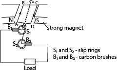
How it works
- The coil is rotated in a magnetic field, the magnetic field linked with it changes and hence e.m.f is led away by means of slip rings which press slightly against the carbon brushes.
- Applying Fleming’s right hand rule, the induced current enters the coil AB and leave the coil via CD.
- Starting with the coil in the vertical position, the magnetic flux linking it is minimum and hence no induced e.m.f.
- The induced e.m.f increases with the position of the coil in the magnetic field until it becomes maximum with the coil in horizontal position and then decrease to zero as the coil rotates to the vertical position
- The force acting on the sides of the coil change as the coil passes over the position and hence he current flowing in the coil reverses. Hence an alternating e.m.f or current flows through the load.
(ii) What are the main energy losses in a practical a.c. generator and how are they minimized? (02marks)
Eddy current loss are minimized by laminating the armature
I2R losses are minimized by use of low resistance winding wires
loss due to friction minimized by lubricating the rubbing parts
(c) A circular coil having 20 turns each of radius 8.0cm is rotated about its vertical diameter with angular speed of 50 radians per second in a uniform horizontal magnetic field of magnitude 30mT.
(i) Calculate the r.m.s value of the e.m.f. induced in the coil (03marks)

(ii) If the coil forms a closed loop of resistance 10Ω, how much power is dissipated as heat in it? (02marks)
![]()
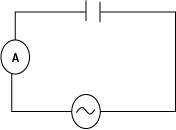
(d) The figure below shows a capacitor and a bulb connected to a.c supply

Explain
(i) Why the bulb lights when switch K, is closed (01marks)
The capacitor is continuously charging and discharging. This cause continuous charge (current) flowthrough the bulb
(ii) What would happen if the capacitance were reduced? (02marks)
When the capacitance is reduced the reactance increases and therefore the charging and discharging current is decrease. The bulb dims or goes off.
(e) Explain the following observation:
(i) A spark is seen at the switch when the circuit of a current carrying coil is broken (02marks)
When the switch is broken, the magnetic flux linking the coil collapses. A large e.m.f is induced between the contacts creating a high electric field intensity which ionizes the air there. The ions meet and neutralize violently producing sparks.
(ii) A magnetized iron bar dropped vertically through a hollow region of a thick cylindrical shell made of copper experiences a retarding force. (02marks)
Magnetic flux linking the shell changes inducing eddy currents that oppose motion of the bar magnet thus causing retardation.
3. (a) Define the following
(i) Peak value(01mark)
Peak value of alternating current is the maximum value attained by such a current in a cycle.
(ii) Root mean square (r.m.s) value of alternating current.(01mark)
Root mean square (r.m.s) value of an alternating current, is the value of steady/direct current that would dissipate heat in a given resistor at the same rate as alternating current.
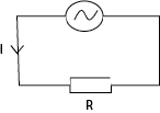
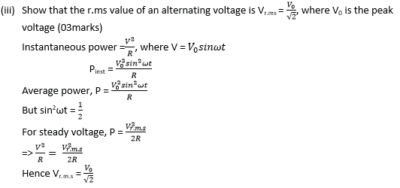
(b) Derive an equation relating peak value and r.m.s value of alternating current (03marks)
Consider an alternating current I = I0sinωt through a resistor, R.
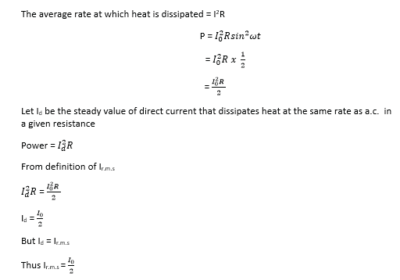
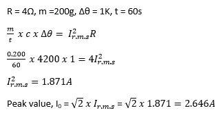
(c) An electric current flow through a coil of 4Ω immersed in 200kg of water placed in a container. If the temperature of the water rises by 1K per minute, calculate the peak value of current supplied. (03marks)
(d) What is meant by resonance in a circuit? (01mark)
Resonance is the condition that exists in a circuit when the inductive reactance and the capacitive reactance are of equal magnitude, causing electrical energy to oscillate between the magnetic field of the inductor and the electric field of the capacitor.
(e) A lamp of resistance 10Ω, a capacitor of capacitance 0.4μF and an inductor of inductance 0.4H are connected in series to an alternating voltage source of 0.01V (r.m.s). The frequency, f, is varied from low to high value while maintaining the amplitude of the applied voltage constant.
(i) Explain how the brightness of the lamp rises. (03marks)
Initially the brightness of the bulb increases as current through the circuit increases with increasing frequency. At resonant frequency, the current through the circuit becomes maximum and the brightness of the bulb becomes maximum. However, the brightness of the bulb dims until it dies off at frequencies greater than the resonant frequency since the current flowing reduces in it.
(ii) Calculate the resonance frequency. (03marks)
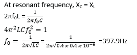
(iii) Find the voltage across the capacitor. (03marks)
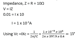
(f) Explain why in an R-C circuit, power is only absorbed by resistive part of the circuit. (02marks)
In one quarter cycle as the capacitor charges, power is transferred from the source to the capacitor. In the next quarter cycle as the capacitor discharges, power is returned to the source.
4. (a) With the aid of a sketch graph, explain the hysteresis curve for ferromagnetic material (07mark)
Solution

- When a magnetic field is applied to a ferromagnetic material, the magnetic domains tend to align with the applied field. The magnetic flux density increases along OA until saturation. When the magnetizing field is reduced to zero, there is residue magnetization at C. This is due to failure of the dipoles to respond instantly. Energy is lost.
- To bring the dipoles to their original orientation, a magnetic field OD is applied in opposite direction. As the magnetic field is increased in this reversed direction, saturation is attained at E
- When reversed magnetic field is reduced to zero, state F is attained. Reversal of dipoles requires an increase of magnetic field in opposite direction to state EF. The cycle is then repeated on further increase of magnetic field
The curve of B verses H is called a hysteresis curve
(b)(i) Describe with the aid of a labeled diagram, the structure and mode of action of a moving coil galvanometer (06marks)
Drawing

Structure
- It consist of a rectangular coil of fine insulated copper wire wound on an aluminium frame to provide electromagnetic damping.
- The coil together with the frame of aluminium are mounted over a soft iron cylindrical core and freely pivoted on jeweled bearing to minimize friction at contact.
- The suspension torsion wire suspending the coil is attached to a pair of control hair springs T1 and T2 for feeding current in and out of the coil and control rotation of the coil.
- The coil is then suspended between concave pieces of a strong magnet to provide magnetic field.
Mode of action
- Current I to be measured is passed into the coil via hair spring T1.
- The current then causes the coil to experience a deflection torque, r = NABI due to a couple force causing rotation in a radial magnetic field.
- The coil turns with the pointer through angle θ until stopped by restoring torque, r = kθ provided by a pair of hair springs T1 and T2.
- At equilibrium, NABI = kθ
![]()
I ∝ θ, hence the instrument has a linear scale
Where B = magnetic field strength between the poles of the magnets
A = area of the plane of the coil
N = number of turns of the coil
k = torsion constant of suspension wire
(ii) Explain why eddy currents are useful in a moving coil galvanometer. (02marks)
Eddy current are induced in the core when the coil moves in magnetic field.
The eddy current damp the oscillations of the coil. This makes the pointer to settle at a point quickly. It is desirable for quick and accurate reading of the value.
(c) A conducting disc of radius 0.05m with its plane perpendicular to uniform magnetic field of flux density 0.25T, rotates at 15 revolution per second about an axis through its center and perpendicular to its plane.
Calculate
(i) Magnetic flux threading the disc at any time (03marks)
Magnetic flux, φ = BA but A = πr2
φ = Bπr2
= 0.25 x 3.14 x (0.05)2 = 1.96 x 10⁻³Wb
(ii) E.m.f generated between the center of the disc and any point on its rim.
ε = Bπr2f = 0.25 x 3.14 x (0.05)2 x 15 = 2.9 x 10⁻²V
or
ε = φf = 1.96 x 10-3 x 15 =2.9 x 10⁻²V
5. (a) state Faraday’s law of electromagnetic induction (01 mark)
The magnitude of e.m.f induced in the circuit is directly proportional to the rate of change of magnetic flux linked with the circuit
(b) With the aid of a diagram describe an experiment to illustrate Lenz’s law of electromagnetic induction. (05marks)
Solution

- The galvanometer is first connected in series with the battery and the coil PQ. The switch K is closed. The direction of deflection of the galvanometer for which current flows in an anticlockwise direction at the end P of the coil is noted.
- The battery is then disconnected and the circuit containing the coil and the switch is made complete.
- A strong permanent magnet is brought towards the coil with a North Pole facing end P of the coil.
- The galvanometer deflects in a direction which shows that the side of the coil facing the magnet is North Pole.
- When the magnet is moved away from the coil, the galvanometer deflects in the opposite direction implying that the pole of the coil near the magnet is a south pole.
- In the first case, the pole due to the induced current was repelling the approaching magnet while in the second case, the pole was attracting the receding magnet.
- The induced current therefore is in such a direction as to oppose the change causing it, which is Lenz’s law
(c) Define magnetic moment of a coil. (01mark)
Magnetic moment is torque experienced by the coil per tesla of magnetic field acting along the plane of the coil.
Or
Magnetic moment of a coil is a couple exerted on a coil when it is placed with its plane parallel to a magnetic field of 1T
(d) A small circular coil of 20 turns of wire lies in a uniform magnetic field of flux density 5.0 x 10⁻²T. The normal to the coil makes an angle of 300 with the direction of the magnetic field. If the radius of the coil is 4cm and the coil carries a current of 2.0A, find the
(i) magnetic moment of the coil (02marks)
M = NIA = 20π x (4 x 10-2)2 x 2 = 0.2Am2
(ii) torque on the coil
T = MBsinθ = 0.2 x 5 x 10-2sin300 = 5.0x 10⁻³Nm
(e) (i) State and define the unit of magnetic flux density.
One tesla (1 T) is defined as the field intensity generating one newton (N) of force per ampere (A) of current per meter of conductor:
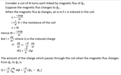
(ii) Show that when the magnetic flux linking a coil changes, the total charge which passes through is depends only on the resistance of the coil and total flux linking it (05marks).
State any two factors which determine the efficiency of a transformer. (01mark)
- Resistance of wire used to make the primary and secondary coils/resistance of windings
- Coupling between the primary and secondary coil
- The design of the core/eddy current in the core
6. (a)(i) What is meant by capacitive reactance? (01mark)
Capacitive reactance is non-resistive opposition flow of a.c. through a capacitor.
(ii) Peak value of an alternating voltage. (01mark)
Peak value of an alternating voltage is the maximum value of the alternating voltage
(b) Distinguish between mutual and self-induction. 02marks)
Mutual induction is a production of e.m.f in a conductor caused by change in magnetic field linking it due to change in current due to nearby circuit
while
Self- induction is the production of an e.m.f in a conductor caused by change in magnetic flux linking it due to the change in the current in the same conductor.
(c)(i) Describe with the aid of a diagram, the structure and working of a.c. transformer (02marks)

Transformer consists of two coil of insulated wire, the primary and secondary wound on laminated soft iron core.
When alternating voltage,Vp is connected to primary coil, it drives alternating current in the primary coil.
The alternating current produces a varying magnetic flux φp that link the primary coils inducing a back e.m.f EB in the primary.
The varying magnetic flux, φs links the secondary coil by mutual induction/inducing alternating voltage, Vs in the secondary
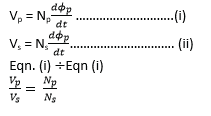
When Ns > Np the transformer is a step up
Ns < Np the transformer is a step down
(ii) Explain the steps taken to minimize power losses in electric power transformation. (03marks)
– Voltage generated is stepped up using a transformer so as to transmit high voltage and low current.
– Low resistance cables are used
(d) In figure below, P is a 6V lamp and Q is a coil of negligible resistance

Explain which of the lamps in the figure above will be brighter when K is closed (02marks)
The bulb in (a) will be brighter.
When the switch is closed in (a), current flows and back e.m.f is induced. This limit s brightness of the bulb. When the current reaches the steady value, the back e.m.f is zero, the bulb lit brightest
In coil (b) the continuous change in direction and quantity of current induces continuous change in magnetic flux and thus back e.m.f and the bulb is dim.
Explain what happens when a soft iron core is introduced in the coil in each of the circuit (03marks)
When soft iron core is introduced, magnetic flux is enhanced in (a), the back e.m.f increases and the current decreases. The brightness of the bulb reduces.
The back e.m.f reduces to zero when the current increases to the maximum (and the change in charge reduces to zero) leading to increase in brightness of the bulb.
In (b) the back e.m.f increases and the current reduces. The brightness of the bulb thus reduces.
7. (a) Define magnetic flux density. (01mark)
Magnetic flux density is the force acting on conductor of length 1m and carrying of 1A placed perpendicular to magnetic field.
(b) Write the expression for the
(i) Magnetic flux density B at a distance r from long straight wire currying current I. (01mark)
![]()
(ii) Force F on a straight wire of length L carrying current I perpendicular to a uniform magnetic field of flux density B.
F = BIL
(c) A moving-coil galvanometer consists of a rectangular coil of N-turns each of area A suspended in a radial magnetic flied of flux density B.
(i) Derive an expression for the torque on the coil when a current I passes through it (04marks)
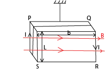
The is no force on the sides PQ and SR since they are parallel to the field
Applying Fleming’s left hand rule, the force initially on PS, F = μBIL (into the plane)
The force initially on QR, F = μBIL (out of the plane)
These force constitute a couple whose moment is given by
Torque, τ = F x b
= μBIL x b
But L x B = A
∴ torque, τ = μBIA
(ii) If the coil is suspended by a torsion wire for which the couple per unit twist is C, show that the instrument will have a linear scale.(03mark)
Torque on the coil, τ = μBIA
Torque due to torsion wire, τ = Cθ
At balance, Cθ = μBIA

Since, μ, B, C and A are constant
θ∝I, the scale is linear
(ii) How can current sensitivity of the instrument be measured? (02marks)
The instrument is connected in series with an ammeter to a voltage source. The current measured, and the deflection, θ, of the instrument is recorded.
Current sensitivity is given by, SI = θ/I
(d) Describe an experiment to determine the magnetic flux density of a uniform magnetic field using a search coil and ballistic galvanometer
Solution

- A search coil of cross section area A and number of turns, N, is connected in series with ballistic galvanometer.
- The search coil is then placed in uniform magnetic field such that the plane of the coil is perpendicular to the magnetic field.
- The coil is then pulled completely out of the field. The first deflection of the ballistic galvanometer noted θ1.
- A capacitor of known capacitance C is then charged to a p.d. V and then charged through the ballistic galvanometer, θ2 is noted
The magnetic flux density of uniform magnetic field is obtained from

Where R is the resistance of the whole circuit.
(e) Figure 2 shows an ampere balance, wires AB and CD each of length 100cm, lie in the same vertical plane and separated by 2.0mm.

When a current I is passed in opposite direction through the wires, a mass of 0.3g is placed in the pan to obtain balance. Find the value of the current I
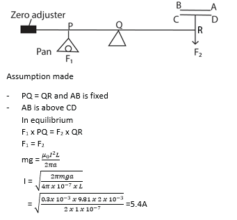
Alternatively if CD is above AB force at P is downward and force R is upwards. Hence equilibrium will not be attained.
Or
Both forces produce a turning effect in the same direction. Equilibrium will not be attained.
8. In the figure below X and Y are smooth conducting rails connected to a source of e.m.f, E. CD is a metal rod of length L m placed horizontally on X and Y perpendicular to magnetic field of flux density B

Copy the diagram and indicate the direction of Force acting on the rod. (01mark)

Using the principle of conservation of energy, show that F = BIL, where I is the current supplied by the source. (04marks)
Induced e.m.f, ε = BLV where V is the velocity of the rod.
Let I be the current induced, electrical power generated = EI
Mechanical power spent = FV
∴ from the principle of conservation of energy, FV = EI
= BIVL
Force, F = BIL
(b) (i) Describe the feature of earth’s magnetic field (05marks)
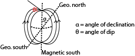
Geographical meridian is the vertical plane containing the geographical axis
Magnetic meridian is the vertical plane containing magnetic axis.
Angle of dip varies from 00 at the magnetic equator to 900 at the poles.
(ii) Sketch the resultant magnetic flux around a wire carrying current vertically upwards in in earth’s magnetic field. (02marks)

(c) A circular coil of 50 turns and radius 0.5m is placed with its plane perpendicular to earth’s magnetic meridian. It is connected to a ballistic galvanometer of sensitivity 5.7 x 10³ radC-1 and circuit resistance of 100Ω. When the coil is rotated through 1800 about a horizontal axis, the galvanometer deflects through 0.8 rads.
Calculate
(i) Horizontal component of earth’s magnetic flux density. (04marks)

p.d across a solenoid of 2000 turns per meter and resistance 5Ω that produces the same magnetic flux density as calculated in (c)(i). (04marks)

9. (a) Define root mean square value of an alternating current. (01mark)
Root mean square value of an a.c. is the value of stead current which dissipates heat at the same rate in a given resistor as alternating current.
(b)(i) Write down and expression for the e.m.f generated by a dynamo and use it to identify the factors which determine the maximum e.m.f. (04marks)
Induced e.m.f , E = 2πfμABsin2πft
Maximum e.m.f, E0 = 2πfμAB
Maximum e.m.f thus increases with increase in
Frequency or angular velocity
Number of turns of the coil
Magnetic flux density
(ii) Explain the structural modification needed to convert an a.c. generator into a d.c. generator.
The slip rings are replaced by commutators and the brushes are arranged so that the changeover of contacts occur over each half a cycle
(c) An iron-cored coil having a low resistance and high inductance is connected in series with a filament lamp, P. the coil and lamp are connected across a d.c. supply as shown in the figure below

Explain what is observed when switch K is closed and then opened. (04marks)
When K is closed bulb P lights dimly and increases to full brightness. This is because when K is closed and current begins to flow, back e.m.f is induced in the coil which opposes the flow of current in the circuit. Gradually the back e.m.f reduces to zero because current reaches maximum (and the change in induced magnetic field reduce to zero) and brightness increases.
When switch K is opened, bulb goes off immediately since there is no current.
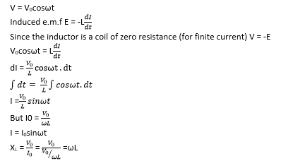
(d) An alternating voltage V = V0cosωt is connected across an inductor of inductance L.
(i) Derive the expression for the reactance of the inductor, XL. (04marks)
(ii) Sketch using the same axes the variation of applied voltage and current through the inductor with time. (02marks)

(e) Describe how a thermocouple ammeter is used to measure an alternating current. (03marks)
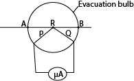
- P and Q are dissimilar wires
- Current to be measured is passed through the wire AB and heats the junction R of the thermocouple.
- The thermoelectric effect generated at R causes a direct current to flow through the micrometer calibrated to measure the r.m.s value of current.
10. (a) (i) what is the difference between a motor and a dynamo? (01mark)
A dynamo converts mechanical energy to electrical energy while a motor converts electrical energy into mechanical energy.
(ii) Describe with the aid of a labelled diagram the structure and mode of operation of a d.c generator. (06marks)
Diagram
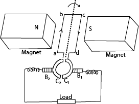
- B1 and B2 are carbon brushes, C1 and C2 are split ring commutators and abcd is a rectangular coil
- When the coil rotates at uniform velocity in magnetic field, e.m.f is induced in it.
- When the coil is in vertical position, the commutators change brushes C1 to B2 and C2 to B1.
- E.m.f reverses direction but the current does not change direction. Hence current flows in the same direction in a resistor.
(iii) Describe briefly the factors that determine the peak value of the induced e.m.f. (03 marks)
The peak value of induced e.m.f increases with increase in
The number of turns in the coil
The area of the coil
The strength of the magnetic field
The frequency of rotation of the coil
(iv) How can a d.c. generator be converted into an a.c. generator. (01mark)
To convert a d.c. generator to an a.c. generator, the ends of the rectangular coil are connected to a pair of slip rings instead of the commutators.
(b) Figure below shows two wires AB and Cd of length 5.0cm each currying a current of 10.0A in the direction shown. A long conductor carrying a current of 15A is placed parallel to the wire CD 2.0cm below it.

(i) Calculate the net force on the long wire (06marks)
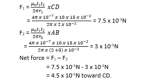
(ii) Sketch the magnetic field pattern between the long wire and wire CD after removing wire AB. Use the field pattern to define a neutral point (03marks)
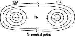
A neutral point is appoint where two magnetic field are equal and opposite and the resultant is zero.
11. (a) What is meant by the following as applied to the earth’s magnetic field?
(i) Magnetic meridian (01mark)
Magnetic meridian is a vertical plane in which a freely suspended magnet sets itself.
Magnetic variance (01mark)
Magnetic variation is the angle between the magnetic and geographical meridians.
Or,
angle between the earth’s magnetic axis and geographical axis.
(b) Describe the structure and mode of action of the deflected magnetometer (06marks)
It is used to compare magnetic moments of magnets
It consists of a small compass needle (small magnet) which is pivoted on a vertical axis and carries alight aluminium pointer. The pointer can rotate over a circular scale (0-900)

The deflection magnetometer is used to compare two magnetic field flux densities, one being the horizontal component of the earth’s flux density BH.
The two fields i.e. BH and any other field to be compared are arranged at right angles to each other. The compass needle then sets itself at angle, θ, to its initial direction when it was in the field BH alone.
The needle now points in the direction of the resultant field of BH and B.
The angles of deflection θ1 and θ2 of the needle are measured.

(c) A circular coil of four turns and diameter 11cm has its plane vertical and parallel to the magnetic meridian of the earth. Determined the resultant magnetic flux density at the center of the coil when a current of 0.35A flows in it.
(Take the horizontal component of the earth’s magnetic flux density to be 1.6 x 10⁻⁵T) (04marks)
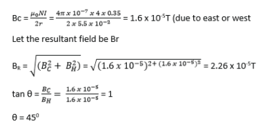
(d) (i) Define self-induction and mutual induction (02marks)
Self – induction is the generation of e.m.f in a circuit (coil) due to a change in the current in the same circuit; and mutual induction is the generation of e.m.f in a circuit (coil) due to a change in current in adjacent but separate circuit.
(ii) Give the causes of power loss in an a.c. transformer and state how each can be minimized. (04marks)
| Cause of power loss | Means of minimizing the loss |
| Ohmic loss | Use of thick copper wires |
| Eddy currents | Use of a laminated core |
| Magnetic flux leakage | Winding secondary coil on primary coil |
(iii) Explain why the current in the primary coil of a transformer increases when the secondary is connected to the load.
When load is connected to the secondary winding, a current flows in it. The current flows in such a direction as to reduce the back e.m.f in primary coil, hence the current increase.
12. (a) Define root mean square (rms) value of alternating voltage (01mark)
Root mean square value (r.m.s) of an alternating current is the steady current which would dissipate heat at the same rate in a conductor as the a.c.
(b) A resistor of resistance 100Ω is connected across an alternating voltage, V = 20sin120πt.
(i) Find the frequency of the alternating voltage (01mark)
ω = 2πf
120π = 2πf
f = 60Hz
(ii) Calculate the mean power dissipated in the resistor. (03marks)
![]()
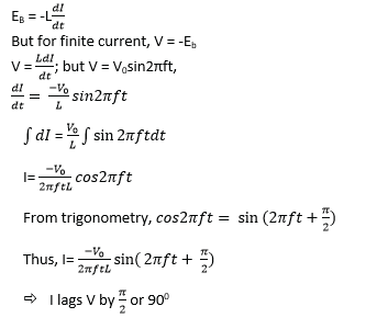
(c) (i) Show that when an inductor s connected to an a.c supply voltage of V = V0sin2πft, the resulting current lags the voltage by 900. (04marks)
(ii) Sketch on the same axes the variation with time of the voltage and current is a capacitor is connected to the voltage supply in (c)(i). (02marks)
Graph

Explanation
- The current I through (not across) a capacitor is
 .
. - This is the slope of the voltage.
- When a capacitor is connected to an a.c. voltage (at the zero crossing) the maximum current flow will occur immediately, i.e. t = 0, (dV)/dt will approach infinity instantly and then repeat as a sinusoidal waveform.
- There will be a peak current at every zero crossing of the voltage waveform. The current waveform will lead the voltage waveform 90 degrees.
(d) (i) Describe how thermocouple meter works. (04marks)

- P and Q are dissimilar wires
- Current to be measured is passed through the wire AB and heats the junction R of the thermocouple.
- The thermoelectric effect generated at R causes a direct current to flow through the micrometer calibrated to measure the r.m.s value of current.
(ii) Explain any precautionary measure taken in the design of thermocouple meter (02mark)
The fine wire is enclosed in an evacuated glass bulb to shield it from draughts. If the wire was in the open, some heat would be lost to the surrounding so that the temperature difference between the hot and cold junctions would not be proportional to the power dissipated in the wire.
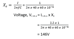
(e) A capacitor of capacitance 60μF is connected to an a.c. voltage supply of frequency 40Hz. An a.c ammeter connected in series with the capacitor reads 2.2A. Find the p.d across the capacitor. (03marks).
13. (a) What is meant by the following as applied to the earth’s magnetic field?
Magnetic meridian (01 mark)
Magnetic meridian is the vertical plane through the magnetic north and south poles of earth’s magnet.
Angle of dip (01marK)
Angle of dip is the angle between the resultant earth’s magnetic field and horizontal.
(b) (i) Define the ampere (01mark)
The ampere is steady current flowing in negligible cross-section, one meter apart in vacuum when the force between them is 2 x 10⁻⁷NM-1.
(ii) there conductors P, Q and R carrying currents 3A, 6A and 8A respectively are arranged as shown in the figure below

Calculate the force experienced by conductor P. (06marks)

(d) (i) Define magnetic flux and magnetic flux density (02marks)
Magnetic flux is the product of the magnetic flux density and the projection of the area normal to the magnetic field.
Or
Magnetic flux density is the force acting on a conductor of length 1m carrying current of 1A placed perpendicular to magnetic field.
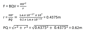
(ii) A charge particle of mass 1.4 x 10⁻²⁷kg and charge 1.6 x 10⁻¹⁹C enters a region of uniform magnetic field of flux density 0.2T at point P and emerges at a point Q as shown in the figure below

If the speed of the particle is 107ms-1, calculate the distance PQ. (04marks)

The conductor describes a circle of radius, r.
(d) Describe an experiment to measure the magnetic flux density between the pole pieces of a strong magnet. (05 marks)
Solution

A search coil is connected to a ballistic galvanometer. The coil is then placed with its plane normal to the magnetic field whose magnetic flux density, B is required.
The coil is then pulled completely out of the field and deflection θ1 of ballistic galvanometer is noted
![]()
A capacitor of known capacitance Q is charged to a p.d. V and is then discharged through the ballistic galvanometer. The deflection θ2 is noted
CV = Cθ2
The magnetic flux density B is now calculated from
![]()
where A is the area of the coil, N is the number of turns in the coil and R is the resistance of the coil circuit.
14. (a) (i) State the laws of electromagnetic induction (02marks)
Lenz’s law of electromagnetic induction; the induced e.m.f acts in such a direction as to oppose the change causing it
Faraday’s law of electromagnetic induction; the magnitude of induced e.m.f in a conductor is directly proportional to the rate of change of magnetic flux linking it.
(ii) Describe with aid of a diagram, an experiment to verify Faraday’s law of electromagnetic induction (05marks)
Diagram
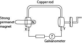
- X and Y are brush contact.
- A copper rod which can rotate round the north pole of permanent magnet is connected as shown above.
- The wheel is turned steadily until the deflection of the galvanometer is constant.
The time, t, for N rotations is measured and the number of revolution (n) per second is determined from n = N/t. - The deflection θ of the galvanometer is also noted.
- The experiment is repeated at different speed of rotation of the wheel and values of n and θ tabulated.
- A plot of θ against n gives a straight line graph implying that θ ∝ n
- Since θ ∝ e.m.f induced and n ∝ speed of rotation of the rod, then the induced e.m.f is proportional to the rate of change of flux linkage.
(b) Explain
(i) Why when a plate of copper is pushed into a strong magnetic field between the poles of a powerful electromagnet, considerable resistance to the motion is felt, but no such effect is felt with a sheet of glass.
When the copper plate cuts the magnetic field and Eddy currents are induced in it
The magnetic field due to Eddy currents interacts with the applied field opposing the motion.
Glass is an insulator no eddy current is induced in it hence no resistance to its motion.
(ii) How damping is achieved in moving coil galvanometer (03marks)
The coil is wound on an iron core. When the coil (together with the core) rotates in the magnetic field, Eddy currents are induced in the core. The magnetic field due to the Eddy currents interacts with the applied field causing retardation (opposing the rotation) of the coil. So the coil comes to rest sooner than it would for accurate reading.
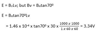
(c) An aero plane of wing span 30m flies horizontally at a speed of 1000kmh-1.
What is the p.d across the tips of its wings, if the horizontal component of the earth’s magnetic field is 1.46 x 10⁻⁴T? (Angle of dip at the place is 700) (03marks)
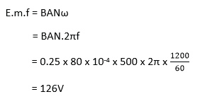
(d) A coil of 500 turns and area 80cm2 is rotated at 1200 revolution per minute about an axis perpendicular to its plane and magnetic field of flux density 0.25T.
Calculate the maximum e.m.f induced in the coil (03marks)
15. (a) (i) Define root mean square (r.m.s) current of an a.c (01mark)
It is a steady current which converts electrical energy to other forms of energies in a given resistor at the same rate as the alternating current.
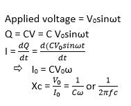
(ii) Derive an expression for capacitive reactance (04marks)
(iii) Sketch on the same axes, the graphs showing variation of applied p.d and current when an inductor is connected to an a.c. supply. (02marks)

Note that the current starts at zero and rises to its peak after the voltage that drives it, i.e., it is voltage that drives current.
(b) (i) A capacitor of capacitance, C, and an ammeter are connected in series across an alternating voltage, V, of frequency f. Explain why current apparently flow through the capacitor. (03marks)
Diagram
When the circuit is completed, the ammeter deflects indicating that current is flowing in it.
When the circuit is closed, the capacitor charges and discharges in opposite direction alternatively. Charge (current) therefore flows in the circuit continuously and the capacitor appears to conduct current.
(ii) A sinusoidal p.d of r.m.s value of 20V and frequency 50Hz is applied across a 100μF capacitor. Calculate the capacitive reactance of the circuit. (02 marks)
![]()
(c) Describe the mode of operation of a transformer. (04marks)

Transformer consists of two coil of insulated wire, the primary and secondary wound on laminated soft iron core.
When alternating voltage,Vp is connected to primary coil, it drives alternating current in the primary coil.
The alternating current produces a varying magnetic flux φp that link the primary coils inducing a back e.m.f EB in the primary.
The varying magnetic flux, φs links the secondary coil by mutual induction/inducing alternating voltage, Vs in the secondary

When Ns > Np the transformer is a step up
Ns < Np the transformer is a step down
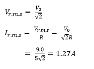
(d) A transformer connected to a.c supply of peak voltage 240V is to supply a peak voltage of 9.0V to a mini-lighting system of resistance 5Ω. Calculate the
(i) r.m.s current supplied to the lighting system (02marks)
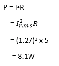
(ii) average power delivered to the lighting system. (02marks)
16. (a) State the laws of electromagnetic induction (02marks)
Faraday’s law states that the magnitude of the e.m.f induced in a circuit is directly proportional to the rate of change of magnetic flux linked with the circuit.
Lenz’s Laws states that induced current flows always in such a direction as to oppose the change which is giving rise to• it.
(b) Describe a method of measuring the magnetic flux density in the region between the poles of a magnet. (06marks)
Solution

A search coil is connected to a ballistic galvanometer. The coil is then placed with its plane normal to the magnetic field whose magnetic flux density, B is required.
The coil is then pulled completely out of the field and deflection θ1 of ballistic galvanometer is noted
![]()
A capacitor of known capacitance Q is charged to a p.d. V and is then discharged through the ballistic galvanometer. The deflection θ2 is noted
CV = Cθ2
The magnetic flux density B is now calculated from
![]()
where A is the area of the coil, N is the number of turns in the coil and R is the resistance of the coil circuit.
(c) Two straight parallel wires A and B carrying steady currents IA and IB respectively are placed close to each other as shown in figure below

(i) Sketch the resultant magnetic field pattern (02marks)
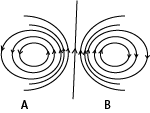
(ii) Explain what happens when the current IA and IB are steady currents. (04marks)
When the two circuit carrying conductors are placed near each other, the conductors repel each other. If the current IA and IB are steady, the resultant magnetic field is constant.
The force acting per meter length,

Therefore the force is constant.
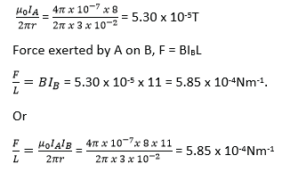
(iii) Find the force per unit length of the wires when IA = 8.0A , IB =11.0A and r = 3.0cm (04marks)
The magnetic flux density which A produces at B is given by
(d) Explain how eddy currents are produced (02marks)
When a conductor cuts through a magnetic field, the magnetic flux linking it changes. This cause small currents to flow in loops in the conductor. These induced currents are called Eddy currents
17. (a) (i) Write an expression for the force exerted on a straight wire of length, L meters carrying a current, I, amperes, placed at right angles to a uniform magnetic field flux density B teslas. (01 marks)
F = BIL
(ii)Explain the origin of the force n (a) (i). (04marks)
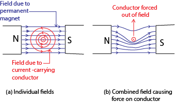
- The current sets up a magnetic field around the wire.
- When the field due to current interacts with external magnetic field, the resultant magnetic field has greater flux density on one side than the other; in the diagram above, high flux density is created below than above.
- The wire moves from a region of greater to lower flux density; thus it move up in this case.
(b) A rectangular coil of N turns each of length, L, and breadth, b, is inclined at an angle θ to a uniform magnetic field of flux density B. Derive an expression for torque of the coil when a current I is passed through it.
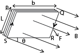
- When current flows through the coil, the conductor experiences a magnetic force.
- Force on side PQ = NBIbsinθ (downwards) while Force on side RS = NBINsinθ (upwards). The two forces cancel out due to rigidity of the coil.
- Side PS experiences force NBIL perpendicularly into the page while RQ experiences force NBIL perpendicularly out of page.
- The two forces constitute a couple whose moment of force
T = F x bcosθ
= NBILbcosθ
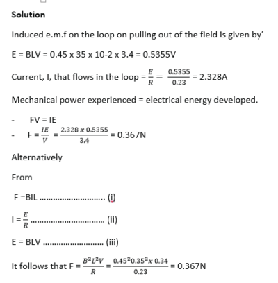
(c) A single rectangular loop of wire with dimensions 35cm by 75cm is arranged such that part of it is inside a region of uniform magnetic field of flux density 0.45T and part of it is outside the field. The total resistance of the loop is 0.23Ω. Calculate the force required to pull the loop from the field at a constant velocity of 3.4ms-1 perpendicular to the field. (05marks)
(d)(i) Define the term magnetic flux. (01marks)
Magnetic flux is the product of magnetic flux density and projection of the area at right angles to the magnetic field
(ii) An electron resolves in a circular orbit of radius 2.0 x 10⁻¹⁰m at a frequency of 6.8 x 10¹⁵ revolution per second. Calculate the magnetic flux density at the center of the orbit (04marks)
The circulation of the electron constitute a current

(a)(i) What is a sinusoidal alternating current? (01mark)
A sinusoidal a.c is aperiodic current whose time dependence is given by sine function.
(i) Define peak value, root mean square (r.m.s) value and frequency of alternating current. (03marks)
Peak value is the maximum value of an alternating current.
Root mean value is the value of direct current which dissipates heat in a given resistor at the same rate as the a.c.
Frequency of alternating current is the number of complete cycles which the current goes through in one second.
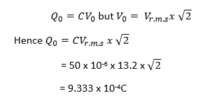
(b) A sinusoidal voltage of r.ms value 13.2V is connected across a 50μF capacitor.
(i) Find peak value of the charge on the capacitor (02marks)
Sketch using the same axes the graphs of charge Q on the capacitor and current I in the circuit against time. (02marks)

- Explanation of the curve
The current I through (not across) a capacitor is
- This is the slope of the voltage.
- When a capacitor is connected to an a.c. voltage (at the zero crossing) the maximum current flow will occur immediately, i.e. t = 0,
 will approach infinity instantly and then repeat as a sinusoidal waveform.
 - There will be a peak current at every zero crossing of the voltage waveform. The current waveform will lead the voltage waveform 90 degrees.
(iv) If the frequency of the alternating current is 49.6Hz, calculate the r.m.s value of current through the capacitor. (03marks)

(c) Explain why a capacitor in a circuit blocks the flow of direct current but allows the flow of alternating current. (04marks)
When a capacitor is connected to a d.c. source the capacitor charges and when it is fully charged, current flow stops.
When it is connected to an a.c, it charges when the voltage is increasing and discharges when the voltage is decreasing. Since increase and decrease in voltage is continuous, there is continuous flow of current in the circuit. Hence a capacitor allows flow of a.c.
(d) Describe the structure and mode of operation of the repulsion type moving iron meter. (05marks)
Diagram

When a current is passed through the coil, the iron rods magnetize in the same poles adjacent to each other in whatever the direction of current. Hence they repel and the pointer move in the same direction until it is stopped by the restoring spring.
Since the magnetic force is proportional to the square of the average current, hence, the deflection is proportional to the square of average current.
Advantage: it measured both direct and alternating current.
Disadvantage: it has nonlinear scale
19. (a) Define the following:
Magnetic flux density (01mark)
Magnetic flux is the product of the magnetic flux density and the projection area normal to the magnetic field.
Magnetic flux linkage (01mark)
Magnetic flux linkage is the product of the magnetic flux density and the area it links perpendicularly.
(b) (i) A rectangular coil of N turns, length, L and breadth, b, carrying a current, I, is placed with its plane making an angle, θ, to a uniform magnetic field of flux density, B. Derive the expression for torque exerted on the coil. (05marks)

- When current flows through the coil, the conductor experiences a magnetic force.
- Force on side PQ = NBIbsinθ (downwards) while Force on side RS = NBINsinθ (upwards). The two forces cancel out due to rigidity of the coil.
- Side PS experiences force NBIL perpendicularly into the page while RQ experiences force NBIL perpendicularly out of page.
- The two forces constitute a couple whose moment of force
T = F x bcosθ
= NBILbcosθ
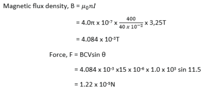
(ii) A current of 3.25A flows through a long solenoid of 400 turns and length 40.0cm.
Determine the magnitude of force exerted on a particle of charge 15.0μC moving at 1.0 x 10³ms-1 through the center of the solenoid at an angle of 11.50 relative to the axis of the solenoid. (04marks)
(c) Describe with the aid of a diagram, an absolute method of measuring current. (06marks)
Current balance is based on principles of moments
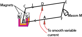
- The apparatus setup is as above, AB = AF, length BC = L and the current through the wire is A
The magnets provide a uniform magnetic field, B, perpendicular to wire BC.
At equilibrium when the frame BCEF is balanced
The force exerted on the wire = weight of the mass
BIL = Mg

Sources of error
- Accuracy of length L
- Rigidity of the frame
- To avoid overheating, the current should be switched off as soon as measurements have been taken.
- Shield the set-up from the disturbance of wind.
(d) Explain why a current carrying conductor placed in a magnetic field experiences a force. (03marks)

The current sets up magnetic field around the wire.
When the field due to current interacts with external magnetic field, the resultant magnetic field has greater flux density on one side than the other; in the diagram above, high flux density is created below than above.
The wire moves from a region of greater to lower flux density; thus it move up in this case.
19. (a) (i) State Lenz’s law of electromagnetic induction (01mark)
The Induced current flows always in such a direction as to oppose the change which is giving rise to it.
(ii) Describe an experiment to demonstrate Faraday’s law of electromagnetic induction. (06marks)
Faraday’s law of electromagnetic inductions states that the magnitude of induced e.m.f in a conductor is directly proportional to the rate of change of magnetic flux linking it.
Diagram

- X and Y are brush contact.
- A copper rod which can rotate round the north pole of permanent magnet is connected as shown above.
- The wheel is turned steadily until the deflection of the galvanometer is constant.
The time, t, for N rotations is measured and the number of revolution (n) per second is determined from n = N/t. - The deflection θ of the galvanometer is also noted.
- The experiment is repeated at different speed of rotation of the wheel and values of n and θ tabulated.
- A plot of θ against n gives a straight line graph implying that θ ∝ n
- Since θ ∝ e.m.f induced and n ∝ speed of rotation of the rod, then the induced e.m.f is proportional to the rate of change of flux linkage.
(b) The figure below shows a piece of metal swing in between opposite magnetic poles
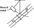
Explain what will be observed after some period of time (04marks)
The amplitude of oscillation reduces gradually until oscillation stop because as the metal is oscillated, it cuts the magnetic field between the poles. Eddy currents are induced in the metal whose magnetic field oppose the oscillation thus causing the oscillation to slow down.
(c)(i) Define the term self-induction and mutual induction. (02marks)
Self-induction is the process by which e.m.f is induced in a circuit due to changing current in the same circuit.
Mutual induction is the process by which e.m.f is induced in a circuit due change in current in the nearby circuit.
(ii) Describe an experiment which can be used to demonstrate self-induction. (03marks)
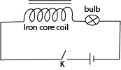
- An iron cored coil is connected in series with a bulb, cell and switch as shown above.
- When K is closed, the bulb lights dimly and then its brightness is increased to maximum.
- The initial current is small due to large back e.m.f and then increases to the maximum because back e.m.f finally reduce to zero.
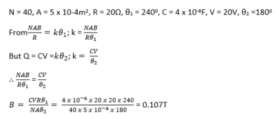
(d) A search coil has 40 turns of wire and cross section area of 5cm2. The coil is connected to a ballistic galvanometer and then with its plane perpendicular to uniform magnetic field of flux density B.
When the coil is withdrawn from the field, the galvanometer gives a deflection of 240 divisions. When a capacitor of 4μF is charged to 20V and then discharged through the circuit, the galvanometer deflection is 180 divisions. Find the value of B, if the total resistance of the circuit is 20Ω. (04marks).
20. (a) What is meant by the terms reactance and impedance as applied to alternating currents. (02marks)
Reactance is non resistive opposition to the flow of a.c in a circuit containing either an inductor or a capacitor.
Impedance is the resultant opposition to flow of a.c in circuit containing reactive and resistive components.
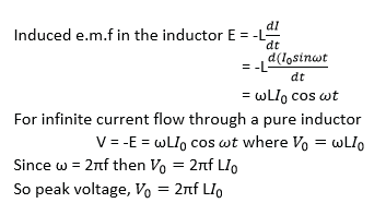
(b)(i) A source of sinusoidal current of amplitude I0 and frequency, f, is connected across a pure inductor of inductance, I, Derive an expression for the peak voltage across the inductor. (04marks)
(ii) Sketch using the same time axis, graphs to show variations of the voltage across the inductor and current through it. (02marks)

(c) An alternating current I = 5sin 200πt, flows through a pure inductor of inductance 2.0H. Calculate the
(i) reactance of the inductor. (03marks)
XL= 2πfL, From I = 5sin200πT, => f = 100Hz
Hence
XL = 2π x 100 x 2 = 1256Ω
(ii) root mean square value of the voltage across the inductor. (03marks)

(d)(i) Explain how an alternating current can be measured using a rectifier meter (04marks)
When a.c is supplied to a rectifier meter, current flows in only one direction. Current flows in the half cycle for positive bias of the diode and in the next half cycle current flow is zero. The characteristics is shown below
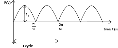
When the frequency is high, the ammeter reads a steady r.m.s value of the current.
(ii) Explain why a moving coil ammeter is unsuitable for measuring alternating current. (02marks)
When an a.c is passed through a moving coil ammeter, the direction of the couple changes every time the current reverses. With high frequency, the pointer only vibrates about the zero position hence the value of the current cannot be read
(a) Define the following:
Weber (01mark)
The weber is magnetic flux that passes normally though an area of 1m2. When the magnetic flux density is 1T.
Ampere (01mark)
The ampere is a steady current which when flowing in each of two infinitely long straight wire parallel conductors of negligible cross section area and 1 meter apart in a vacuum produces between the wires a force of 2.0 x 10⁻⁷N per meter of the length.
(b) A circular coil of N turns, each of radius R carries a current I.
(i) Write an expression for the magnetic flux density at the center of the coil (01mark)
![]()
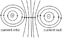
(ii) Sketch the magnetic field pattern associated with the coil. (02marks)
(c) Describe how deflection magnetometer can be used to investigate the variation of magnetic flux density at the center of a circular coil with the current flowing through the coil. (06marks)
The circular coil is set with its plane in the earth’s magnetic meridian. A deflection magnetometer is mounted on a vertical axis at the center of the circular coil, with its pointer initially at the zero mark. The coil is then connected through a reversing switch to a battery, rheostat and an ammeter. Adjust the rheostat so that the ammeter a suitable value of I.
The deflection θ1 and θ2 are noted. The procedure is repeated for other suitable values of I and the results tabulated including values of
![]()
and tan θ.
A graph of tan θ against I is plotted and it is linear. This shows that tan θ is proportional to I
Since B = BHtan θ, where BH is horizontal component of the earth’s magnetic flux density.
This implies that B ∝ I
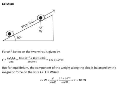
(d) Two parallel wires P and Q, each of length 0.2m carry currents of 10A and 1A respectively
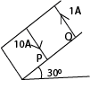
The distance between the wires is 0.04m. If both wires remain stationary and the angle of the plane with the horizontal is 300. Calculate weight of Q.
(e) (i) State why the damping in the ballistic galvanometer should be as small as possible. (01mark)
When the oscillation in the ballistic galvanometer is damped, the deflection is not proportional to the charge.
(ii) Describe how the damping can be reduced in practice (03marks)
Damping in ballistic galvanometer is reduced in the following ways
- Winding the coil on non-conducting frame
- Using a heavy coil so that it has a large inertia
- Using a fine suspension so as to increase the period of oscillation.
23. (a)(i) Define the terms self-induction and mutual induction. (02marks)
Self-induction is a process of generating e.m.f in a coil due to changing current in the same coil.
Mutual induction is a process of generating e.m.f in a coil due to changing current in neighboring coil.
State Faraday’s law of electromagnetic induction (01mark)
It states that the magnitude of induced e.m.f is directly proportional to the rate of change of magnetic flux linking it.
(b) (i) Describe the structure and action of a.c transformer. (06marks)

Transformer consists of two coil of insulated wire, the primary and secondary wound on laminated soft iron core.
When alternating voltage,Vp is connected to primary coil, it drives alternating current in the primary coil.
The alternating current produces a varying magnetic flux φp that link the primary coils inducing a back e.m.f EB in the primary.
The varying magnetic flux, φs links the secondary coil by mutual induction/inducing alternating voltage, Vs in the secondary

When Ns > Np the transformer is a step up
Ns < Np the transformer is a step down
(ii) Explain why the voltage at a generating power station must be stepped up to very high value for long distance transmission (03marks)
Transmission is at high voltage to reduce power loss
Note that
Power supplied, P =IV
![]()
Hence when V is high, I is small. From power loss, P’ = I2R, when I is small power loss is reduced.
(c) In the figure below, a conducting rod PQ of length 20mm rests on a smooth conducting frame to form a complete circuit of resistance 4.0Ω. When a force, F, is applied, the rod moves at a constant velocity of 6.0ms-1 perpendicular to a uniform magnetic field of flux density 1.5T.
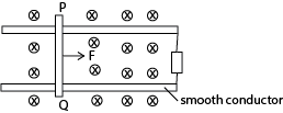
Explain why the rod PQ moves with constant velocity. (03 marks)
- As PQ moves, it cuts the magnetic field and an e.m.f is induced across it. Since the rod is a closed circuit, induced current flows through it.
- By Fleming’s left hand rule, magnetic force acts on the rod in such a way as to oppose the motion.
- When magnetic force = applied force, then the resultant force is zero. Therefore PQ moves with constant velocity.
Calculate the amplitude of the induced e.m.f (02marks)
E = BLV= 1.5 x 20 x 10-3 x 6.0 = 0.18V
Calculate the magnitude of the force, F. (03marks)

24. (a) Define the term peak value and root mean square value of an alternating current. (02 marks)
Peak value is the maximum value of alternating current.
Root mean square value is the value of direct current which dissipates heat in a given resistor at the same rate as the a.c.
(b) A coil of many turns of wire is connected in parallel with an electric bulb to a d.c supply as shown in the figure below.

At the instant switch K is closed, the bulb flashes briefly for a short time and then goes off. Explain the observation.
When switch K is closed, current begins to flow through the coil and the changing magnetic flux due to the change in current induces a back e.m.f in the coil thus most of the current flows through the bulb making it to flash. Latter back e.m.f decay to zero and most of the current then flows through the coil and the bulb goes off.
(c) A sinusoidal alternating voltage of 20V (r.m.s) and frequency 60Hz is applied across a coil of wire of inductance 0.2H and negligible resistance.
(i) Find the reactance of the coil at this frequency. (03marks)
XL = 2πfL
= 2π x 60 x 0.2
= 75.4Ω
(ii) Calculate the r.m.s value of the current which passes through the coil (02marks)

(iii) Explain why on average the power delivered to the inductor in one cycle is zero. (03marks)
During the first quarter cycle, when current increases, work is done against the back e.m.f. The energy supplied by the source is stored in the magnetic field of the coil. During the second quarter cycle, as current begins to decay, the magnetic field begins to collapse and energy is returned to the source. The same process is repeated in the next half cycle. Hence the energy supplied in the cycle to the coil is zero.
(d) Describe with aid of a labelled diagram the structure and action of a hot wire ammeter. (06marks)
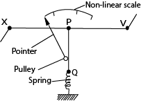
- The current flows through a fine resistance-wire XY, which it heats.
- The wire warms up to such a temperature that it loses heat-mainly by convection-at a rate equal to the average rate at which heat is developed in the wire.
- The rise in temperature of the wire makes it expand and sag; the sag is taken up by a second fine wire PQ, which is held taut by a spring.
- The wire PQ passes round a pulley attached to the pointer of the instrument, which rotates as the wire XY sags.
- The deflection of the pointer is roughly proportional to the average rate at which heat is developed in the wire XY; it is therefore roughly proportional to the average value of the square of the alternating current, and the scale is a square-law one.
25. (a) Define the following terms as applied to alternating voltage
Root mean square value (01 marks)
Root mean square value is the value of direct current which dissipates heat in a given resistor at the same rate as the a.c.
Peak value
Peak value is the maximum value of alternating Voltage.
(b) (i) An alternating voltage is applied across a capacitor of capacitance, C. show that current in the circuit leads the voltage by π⁄2
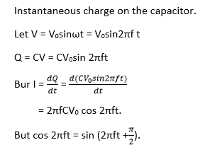
- This shows that the current varies a quarter-cycle out of step with the voltage-or, as is more often said, π/2 out of phase.
- When the voltage is a maximum, so is the charge on the capacitor. It is therefore not charging and the current• is zero.
- When the voltage starts to fall, the capacitor starts to discharge; the rate of discharging, or current, reaches its maximum when the capacitor is completely discharged and the voltage across it is zero.
(ii) Find the expression for capacitive reactance in terms of frequency, f, and capacitance, C.

A capacitor of 0.1μF is in series with an a.c. source of frequency 500Hz. If the r.m.s value of the current flowing is 6mA, calculate the voltage across the capacitor (03marks)

(c) A bulb is connected in series with an inductive coil and a d.c source as shown in the figure below

(i) What happens to the brightness of the bulb when an iron core is inserted in the coil? (01mark)
Initially the bulb dims and latter becomes bright.
(ii) Explain what happens to the brightness of the bulb when the d.c. source is replaced with a.c. and an iron core inserted in the coil. (03marks)
The brightness reduces when d.c is replaced by a.c and reduces further when iron core is inserted in the coil or the bulb may not light at all because the back e.m.f opposes the flow of current through the bulb. The iron core increases back e.m.f
(d) (i) What is hysteresis loss ? (01mark)
Hysteresis loss is the loss in energy due to the change in magnetic domains from one direction to the other as current changes
(ii) How can hysteresis loss be minimized in a.c. transformer? (01mark)
It is minimized by using soft magnetic materials like soft iron and perm alloy in which energy required
(iii) Explain why the primary current in the a.c. transformer increases when the secondary coil is connected to the load? (04marks)
When a load is connected to the secondary, current flows in the secondary which induces magnetic flux in the core in opposition to magnetic flux due to primary current.
Magnetic flux in the core due to primary current thus reduces.
This leads to a reduction in back e.m.f in the primary and hence the primary current increases.
26. (a)(i) Draw a well labelled diagram to show the structure of repulsion type moving iron ammeter (02marks)
Diagram

(ii) Explain how the ammeter in (a)(i) above is able to measure alternating current. (05marks)
- When a current is passed through the coil, the iron rods magnetize with the same poles adjacent to each other in whatever the direction of current.
- Hence they repel and the pointer move in the same direction until it is stopped by the restoring spring.
- Since the magnetic force is proportional to the square of the average current, hence, the deflection is proportional to the square of average current.
Advantage: it measured both direct and alternating current.
Disadvantage: it has nonlinear scale
(b) (i) Write down an expression for magnetic flux density at the center of a flat circular coil, N, turns each of radius, a, carrying current I. (01mark)

(ii) Describe how you would determine the value of the earth’s magnetic flux density at a place, using a search coil. (06marks)

A coil of known number of turns, N (about 100) and area A is connected to a calibrated ballistic galvanometer so that the total resistance in the circuit is R.
The coil is placed in a vertical plane perpendicular to the magnetic meridian of the earth as shown in (i) in figure above. The coil is then rotated through 1800 about the vertical axis. The maximum throw θ1 is noted.
The coil is then placed with its plane in horizontal plane perpendicular to the magnetic meridian of the earth as shown in (ii) in figure above. The coil is then rotated through 1800 about the horizontal axis. The maximum throw θ2 is noted.
Treatment of results

(c) A coil of 50 turns and radius 4cm is placed with its plane in the earth’s magnetic meridian. A compass needle is placed at the center of the coil. When a current of 0.1A passes through the coil, the compass needle deflects through 400. When the current is reversed, the needle deflects through 430 in opposite direction.
(i) Calculate the horizontal component of the earth’s flux density. (04marks)

(ii) Calculate the magnetic flux density of the earth at that place given that the angle of dip at the place is 150.
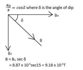
27.(a) State the laws of electromagnetic induction. (02marks)
Faraday’s laws states that the magnitude of the induced e.m.f in a conductor is directly proportional to the rate of change of magnetic flux linking the conductor.
Lenz’s law states that the direction of the induced e.m.f is such that the current which it causes to flow opposes the charge which is producing it.
(b) (i) A circular metal disc of radius R. rotates in an anticlockwise direction at angular velocity, ω, in a uniform magnetic field of flux density, B, directed in to paper as shown in the figure below

A and C are contact points
Derive an expression for e.m.f induced between A and C.
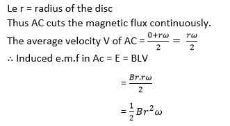
(ii) A copper disc of radius 10cm is placed in a uniform magnetic field of flux density, 0.02T, with its plane perpendicular to the field. If the disc is rotated parallel to the field about an axis through its center at 3000 revmin-1, calculate the e.m.f that is generated between its rim and the centre. (03marks)
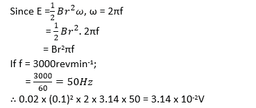
(c) Describe an experiment to demonstrate mutual induction (04marks)
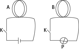
Coil A and B are placed close to each other. When K is closed bulb P lights. Hence e.m.f is induced in B. Since the circuit is closed current flows and the bulb lights.
(d) The diagram in the figure below shows the arrangement by which a laboratory balance is critically damped. The aluminium beam supporting the pan moves in the magnetic field of two powerful magnets.
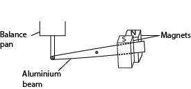
(i) Explain how damping is caused. (03marks)
When the beam moves between the magnetic poles, it cuts the magnetic field. Eddy currents are induced in the beam whose magnetic field opposes its movement. Hence damping the motion.
(ii) What change would occur in the performance of the balance if the magnets were replaced by weaker ones (01mark)
The beam takes longer to settle.
(e)(i) Define the ampere (01mark)
The ampere is the current which when flowing in each of the two long parallel wires of negligible cross-sectional area and 1m apart in a vacuum produces a force of 2 x 10⁻⁷Nm-1 on each other.
(ii) Two parallel wire, P and Q of equal length 0.1m, each carrying a current of 10A are a distance 0.05m apart with P directly above Q. If P remains stationary, find the weight of P. (03marks)
Force due to magnetic field on P = weight of P, W.

28.(a) Define the term magnetic flux density. (01mark)
Magnetic flux density is the force acting on a charge of 1C moving with a velocity of 1ms-1 at right angle to magnetic field.
(b) Write expression for the
(i) magnetic flux density at a perpendicular distance, R, from a long straight wire carrying current, I, in air. (01mark)
![]()
(ii) Force on a straight conductor of length, L (meters) carrying current, I (ampere) at an angle, θ, to a uniform magnetic field of flux density, B (tesla)
F = BILsinθ
(c) Two straight long and straight wires of negligible cross-section area carry currents of 6,0A and 3.0A in opposite direction as shown below

If the wire are separated by a distance of 8.0cm, find the;
(i) Magnetic flux density at a point mid-way between the wires (04marks)
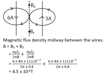
Force per meter between the wire (03marks)
![]()
(d) Define:
(i) angle of dip (01mark)
Angle of dip is the angle between the earth’s resultant magnetic flux density and the horizontal.
(ii) angle of declination (01mark)
Angle of declination is the angle between the earth’s magnetic and geographical axes or angle between the earth’s meridian and geographical meridian.
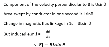
(e) A straight conductor of length, L, is perpendicular to magnetic field of flux density B. If the conductor moves with velocity, U, at an angle θ to magnetic field, derive the expression for e.m.f induced. (04marks)
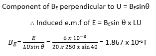
(f) An aircraft of wing 20m is moving horizontally from west to east at a velocity of 250ms-1 in a place where the angle of dip is 400. The e.m.f induced across the tips of the wings is 6mV. Find the magnetic flux density of the earth field. (04mrks)
29. (a) State the laws of electromagnetic induction. (02marks)
The magnitude of the induced e.m.f is directly proportional to the rate of change of magnetic flux linking the circuit or conductor.
The direction of the induced e.m.f is such that it tends to oppose the charge causing it.
(b) The e.m.f generated in a coil rotating in a uniform magnetic field is given by E0sinωt.
(i) State the meaning of the symbols used and give their units. (03marks)
- E0 is the maximum(peak) value of e.m.f in volts
- ω is the steady angular velocity of the coil in radians per second.
- t is time in seconds.
(ii) Draw diagrams showing the relative positions of the coil and the magnetic field when t is zero and when the e.m.f generated is E0. (03marks)

(c) A rectangular coil of 50turnsis 15.0cm wide and 30.0cm long. If it rotates at a uniform rate of 2000 revolution per minute about an axis parallel to its long side and at right angles to a uniform magnetic field of flux density 0.04T, find the peak value of the e.m.f induced in the coil (03marks)

(d)A solenoid of, n, turns per meter, a resistor, R, an ammeter, A, and a rheostat are connected to the battery as shown in the figure below. A disc of radius, r, is mounted inside the solenoid with is axis coincident with that of the solenoid. The center and rim of the disc are connected across, R. The disc is rotated with its plane perpendicular to the axis of the solenoid at a frequency, f.

The rheostat is adjusted until the galvanometer shows no deflection and ammeter reads a current of I amperes.
(i) Show that the e.m.f induced between the center and rim of the disc is πBr2f, where B is magnetic flux density inside the solenoid. (04mar
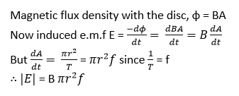
(ii) Deduce an expression for resistance of R, in terms of n, f, I and r.

State two limitations of the above set up in measurement of resistance.
Since the e.m.f generated is very small the method is only used to measure very small resistance.
The earth’s magnetic field affects the induced e.m.f.
The effect of thermal e.m.f generated due to friction at the contact.
30. (a) (i) Distinguish between root mean square value and peak value of an alternating current.
(02marks)
Root mean square value of alternating current is the value of steady or direct current which dissipates heat in a given resistor at the same rate as the alternating current, while peak value is the maximum value of current.
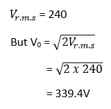
What is peak value of voltage from a 240 a.c mains? (02marks)
(b)

An air-cored coil, a bulb and an a.c. source are connected as shown in figure above. When a solid iron core is introduced in the coil, the bulb becomes dimmer and the core hot. Explain the observation. (06marks)
When the iron core is introduced into the coil, the magnetic flux linkage with the coil increases. The rate of change of magnetic flux linkage with the coil increases, and hence an increase in the induced back e.m.f. This leads to a reduction in the current flowing through the bulb that dims.
The changing magnetic flux in the coil induces Eddy currents in the iron core. These currents cause the core to heat up by I2R mechanism
Secondary, the changing magnetic field continuous reverse magnetization of the core thus reversing the magnetic domains of the core. This leads to heating of the core due to friction between domains or hysteresis.
(c) (i) What is meant by the term inductive reactance? (01mark)
Inductive reactance is non-resistive opposition to flow of alternating current through the inductor.
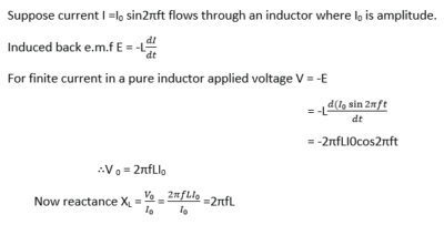
(ii) Derive an expression for reactance of an inductor of inductance L when a sinusoidally varying a.c. of frequency, f, passes through it. (05marks)
(iii) A sinusoidal alternating voltage of 6.0Vr.m.s and frequency 1 kHz is applied to a coil of inductance 0.5H. Assuming that the coil has negligible resistance, calculate the root mean square value of current. (03marks)

(d) State one advantage of a.c over d.c.
a.c can easily and cheaply be changed from one voltage to another.
a.c can easily be transmitted with little power loss
a. c. is cheap to generated
31. (a) Define the terms magnetic flux and magnetic flux density. (02marks)
Magnetic flux is the product of magnetic flux density and the projection of area normal to the magnetic field.
Magnetic flux density is the force acting on a 1m long conductor carrying current of 1A in a direction perpendicular to magnetic field.
(b) A straight wire of length 20cm and resistance 0.25Ω lies at right angles to a magnetic field of flux density 0.4T. The wire moves when a p.d of 2.0V is applied across its ends. Calculate the;
(i) initial force on the wire
![]()
(ii) force on the wire when it moves at a speed of 15ms-1. . (02marks)
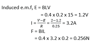
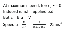
(iii) Maximum speed attained by the wire (02marks)
(c) (i) sketch the magnetic field pattern around a vertical straight wire carrying a current in the earth’s magnetic field and use it to explain a neutral point in magnetic field. (03marks)
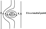
A neutral point is appoint where the resultant magnetic flux (density) is zero
(ii) Two long parallel wires placed 12cm apart in air carry currents of 10A and 15A respectively in the same direction. Determine the position where the magnetic flux is zero. (04marks)
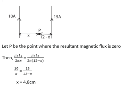
P is 4.8cm from 10A current and 7.2 cm from the 15A current carrying conductor.
(d) Describe with the aid of a diagram, an absolute method of determining resistance. (05mark).
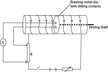
The circuit is connected as above. The metal disc of known radius r, is placed at the center of solenoid carrying current with the plane of the disc perpendicular to magnetic field. The disc is rotated using the driving shaft. The speed of rotation of the disc is adjusted until the galvanometer shows no deflection. The number of revolutions for a given interval of time is counted and the frequency, f, determined.
The resistance is then calculated from;
R =μ0nπr2f;
Where n is the number of turns per meter of the solenoid
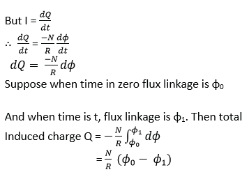
(a) Derive an expression for the charge, Q, induced in a coil of N turns when the
magnetic flux through it changes. (04marks)
(b) (i) Describe how a ballistic galvanometer of an unknown charge sensitivity can be used to measure magnetic flux density in a region between the poles of a magnet. (05marks)
Solution

A search coil is connected to a ballistic galvanometer. The coil is then placed with its plane normal to the magnetic field whose magnetic flux density, B is required.
The coil is then pulled completely out of the field and deflection θ1 of ballistic galvanometer is noted
![]()
A capacitor of known capacitance Q is charged to a p.d. V and is then discharged through the ballistic galvanometer. The deflection θ2 is noted
CV = Cθ2
The magnetic flux density B is now calculated from
![]()
where A is the area of the coil, N is the number of turns in the coil and R is the resistance of the coil circuit.
(ii) State the possible sources of error in above experiment. (02mark)
It may not be possible to get the coil completely out of the field
Improper position of the search coil
Inaccuracy of ballistic galvanometer
Influence of earth’s magnetic flux
(c) A flat circular coil with 2000turns, each of radius 50cm, is rotated at a uniform rate of 600 revolutions per minute about its diameter at right angle to a uniform magnetic flux density 5 x10⁻⁴T4T. Calculate the amplitude of the induced e.m.f. (03marks)

(d) Describe with the aid of a labelled diagram, the structure and action of a hot wire ammeter. (06marks)

- The current flows through a fine resistance-wire XY, which it heats.
- The wire warms up to such a temperature that it loses heat-mainly by convection-at a rate equal to the average rate at which heat is developed in the wire.
- The rise in temperature of the wire makes it expand and sag; the sag is taken up by a second fine wire PQ, which is held taut by a spring.
- The wire PQ passes round a pulley attached to the pointer of the instrument, which rotates as the wire XY sags.
- The deflection of the pointer is roughly proportional to the average rate at which heat is developed in the wire XY; it is therefore roughly proportional to the average value of the square of the alternating current, and the scale is a square-law one.
33. (a) (i) what is meant by peak value of a sinusoidal current? (01mark)
The peak current of a sinusoidal current is the maximum value of the current.
(ii) A source of sinusoidal voltage of amplitude V0 and frequency f is connected across a capacitor of capacitance, C. Derive an expression for instantaneous current which flows (03marks)

(iii) With reference to the circuit in (a)(ii), sketch using the same axes, graphs to show the variation of voltage and current with time. (02marks)
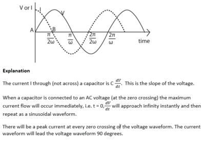
(b)(i) Explain why an alternating current apparently flow through a capacitor whereas a direct current does not. (03marks)
When a capacitor is connected to a d.c source, the capacitor charges fully and current stops flowing.
When the capacitor is connected to a.c voltage supply, the voltage increases and decreases alternatively. When the voltage increases the capacitor charges and when the voltage decreases the capacitor discharges. Hence continuous flow of charge (current) in the circuit.
(ii) Explain the advantages of a.c over d.c in power transmissions. (02marks)
- a.c can easily be stepped up and down
- a.c is easy to generate
- a.c can be transmitted with low power loss.
(c) With the aid of a diagram, describe how a half wave rectifier type of meter works. (04marks)
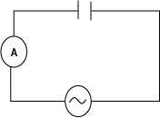
Current to be measured is fed to the meter through rectifier diode in which current flows in only one direction.
So a direct current of varying magnitude flows through the meter. The moving coil meter is calibrated to measure the average current (or Ir.m.s)
(c) A sinusoidal voltage V = 339sin100πt is connected across 40Ω resistor. Find the;
(i) amplitude of the current through the resistor. (02marks)

(ii) average power developed in the resistor. (03marks)

34. (a) Define:
The tesla (01mark)
A tesla (1 T) is defined as the magnetic field intensity generating one newton (N) of force per ampere (A) of current per meter of conductor:
Magnetic flux (01mark)
Magnetic flux is the product of the magnitude of the magnetic flux density and the area perpendicular to the magnetic field.
(b) Two infinitely long straight wire currying currents, I1 and I2 respectively are placed parallel to each other in a vacuum at a distance, d, meters apart. Derive an expression for the force per meter between the wires. (05marks)
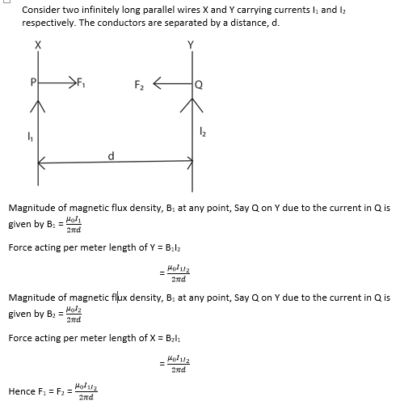
(c)(i) Sketch the magnetic field pattern due to a current flowing in a circular coil. (02mark)

(ii) Write an expression for magnetic field flux density, B, at the center of circular coil of N turns of radius, r, and carrying a current I (01 mark)
![]()
(iii) A wire of length 7.85m is wound into a circular coil, find the magnetic flux density at the center of the coil of radius 0.05m. If the current of 2A passes through the coil, find the magnetic flux density at the center of the coil. (04marks)
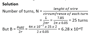
(d) (i) Explain the term back e.m.f in a d.c motor. (02mark)
As the motor rotates the magnetic field, the flux linking changes. This induces an e.m.f in the coil. The e.m.f acts in opposition to applied voltage, hence back e.m.f.
(ii) Show how the back e.m.f in a motor is related to efficiency of motor (04marks)
Suppose Eb, V, and r are the magnitudes of back e.m.f, applied p.d and total resistance respectively.
If I is the current flowing, the power supplied = VI = I2R + IEb
IEb is the rate at which the motor does mechanical work, I2r is the power dissipated in the coil and VI is the power supplied by the motor.

35.(a)(i) Define the terms amplitude and root mean square (r.m.s) value of an alternating current. (02amrks)
Amplitude of an alternating current is the maximum value of alternating current.
Root mean square value of an alternating current is the value of steady current that dissipates heat at the same rate as alternating current.
(b)

A small magnet is attached to a spring as shown above. Switch, K is closed and the magnet is displaced downwards slightly and released to oscillate vertically. Explain
(i) The observation made (03marks)
The galvanometer deflects in one direction when the magnet approaches the coil and deflects in opposite direction when it recedes.
This is because as the magnet moves toward the coil, the flux linking it changes and e.m.f is induced in the coil. Since the circuit is complete, current flows in the direction of the induced e.m.f.
As the magnet moves away from the coil, an e.m.f is induced in the opposite direction.
(ii) Why the magnet takes long to come to rest when K is opened (03marks)
When the switch is open, there will be no flow of induced current that would cause an opposing magnetic field that produce electromagnetic damping. Consequently, the oscillation take long to stop.
(c) A sinusoidal voltage of r.m.s value 10V is supplied across a 50μF capacitor.
(i) Find the peak value of the charge on the capacitor. (02marks)
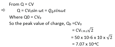
(ii) Draw a sketch graph of charge Q on the capacitor against time. (01mark)
(iii)Draw on the same sketch in (c)(i) a graph of voltage against time. (01mark)

(iv) If the a.c supply has a frequency of 50Hz, calculate the r.m.s value of the current through the capacitor. (04marks)
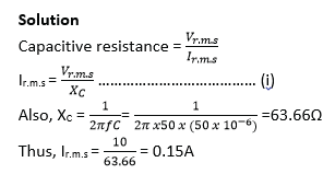
Additional questions download pdf:
Magnetism revision questions (A-level) with answers
Please share with a friend
Thank you so much
Compiled by Dr. Bbosa Science

