 notes")
Magnetism (A-level) notes

Magnetism
It refers to physical phenomena arising from the force caused by magnets, objects that produce fields that attract or repel other objects.
The scope of magnetism include
- Magnetic field patterns of magnets, earth’s magnetic field and current carrying conductors.
- Magnetic field intensity or force
- Magnetic induction
- Applications of magnetism such as relays, solenoids, inductors, chokes, coils, loudspeakers, motors, generators, transformers, and electricity meters etc.
Magnetic field
This is a region of space around a magnet or a moving electric charge within which a force of magnetism acts.
In a magnetic field:
- A magnetic force can be experienced
- A moving charge experiences a magnetic force
- A current- currying conductor experiences a force
- An e.m.f is induced in a moving conductor.
The figure below shows Iron filings attracted to a bar magnet to show the magnetic field.

Magnetic Flux
- All magnets, no matter what their shape, have two regions called magnetic poles; North and South.
- The north of a compass magnet is the end that points towards the Earth’s north.
- Like poles repel, unlike poles attract
- Magnetic fields are lines of force draw from the North to the South of a magnet. The closer the Field lines the stronger the magnetic fields.
- The direction of magnetic field B, at any location is given by the direction of North Pole of the compass needle
- Magnetic field B is measured in N/Am or Tesla, T
Drawings of magnetic field patterns are shown below
Magnetic field lines for a bar and horse Shoe magnet

- Lines of force leave the North-Pole and enter the South Pole.
- An arrow should be drawn to show the direction of field lines
- Lines of force do not cross each other
- Magnetic field is strongest at the poles
Magnetic field lines for two nearby magnets
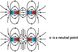
Note that a line of the field will pass in opposite directions if like poles are nearby. A neutral point will be between them. A neutral point a place a round a magnet where a magnetic needle experiences zero magnetic force
Earth’s magnetic field
The earth’s magnetic field lines are made up of parallel lines running from geographical south to geographical north.

The study of the earth’s magnetic field involves:
- Two marginal lines called magnetic meridian and geographical meridian
- Two angles called angles of dip and angle declination
Definitions
Magnetic meridian: This is the vertical plane containing the magnetic axis
Geographic meridian: this is the vertical plane passing through the axis of rotation of the earth.
Magnetic axis: This is the imaginary line passing through the earth’s magnetic North and South Pole.
Geographical axis: This is the imaginary line through the center of the earth and passing through the geographic North and south.
Angle of dip (inclination) α: Angle of dip is the angle that the axis of a freely suspended bar magnet makes with the horizontal when the magnet settles

Generally the angle of dip varies from 00 at the equator to 900at the North Pole.
Magnetic Equator: This is the greatest circle in a horizontal plane perpendicular to the magnetic meridian where a freely suspended bar magnet experiences zero magnetic dip.
Explanation
At the magnetic equator, the earth’s magnetic field lines are parallel to the horizontal. Therefore the angle of dip at the equator is zero, (α =0)
As one moves along a given longitude towards the North Pole, the resultant magnetic field lines meet the earth’s surface at angles greater than 00 but less than 900 thus the angle of dip at such a position is also greater than zero but less than 900. i.e. 00 < α <900.
At the North Pole, the magnetic field lines are normal to the earth’s surface, thus they are perpendicular to the horizontal. Therefore the angle of dip at the North Pole = 900 or α = 900.
Angle of declination (magnetic variance)
This is the angle between the earth’s magnetic and geographical meridians. Or the angle between magnetic north and true north.
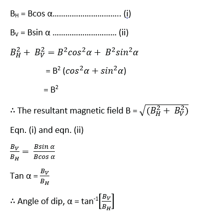
Illustration of the relationship of geographical north, magnetic north, angle of dip and angle of declination

α = angle of dip
θ = angle of declination
BH = horizontal component of the earth’s magnetic field
BV = vertical component of magnetic field
B = resultant magnetic flux density
Magnetic field patterns due to current carrying conductors
When a straight wire or conductor is carrying a steady or direct current, a magnetic fields is created or generated around it. For a straight conductor, the magnetic field pattern is uniform concentric circles around it.
The direction of magnetic field is determined by Right hand grip rule
Right hand grip rule
Imagine gripping the conductor with the thumb straight in the direction of flow of current, with the finger curled around it, the direction in which the fingers point gives the direction of magnetic field around the conductor.
Magnetic pattern due to
(i) Using right hand rule the magnetic field pattern for a conductor carrying current from left to the right can be predicted as follows

(ii) Using right hand rule the magnetic field pattern for a conductor carrying current from right to the left can be predicted as follows

Magnetic field patterns for straight wires carrying a current perpendicularly out of or into the plane of paper as shown in fig (a) and (b) respectively below

Magnetic field pattern due to two nearby current carrying conductors having current flowing in same and opposite direction are shown below

Magnetic field pattern due solenoid carrying a current

- Current in solenoid produces a stronger magnetic field inside the solenoid than outside. The field lines in this region are parallel and closely spaced showing the field is highly uniform in strength and direction.
- Field lines outside the solenoid are similar to that of a bar magnet and it behaves in a similar way – as if it had a north pole at one end and South Pole at the other end.
- Strength of the field diminishes with distance from the solenoid.
- Strength of the magnetic field can be increased by:
-
- increasing the current in the coil
- increasing the number of coils in the solenoid; and
- using a soft iron core within the solenoid.
-
- Reversing the direction of the current reverses the direction of the magnetic field.

Example 1
The diagram shows a piece of soft iron bar suspended freely on a spring balance. One end of the bar is close to the end of the coil connected to a source of e.m.f via switch K.

When switch K is closed, the spring balance reads 50B. State the polarity of AB and explain your observation
Solution
The upper end of the coil is a North Pole (applying right hand rule) when K is closed.
Increase in spring balance reading shows that the iron bar is attracted. Thus A is a south pole while B is the North Pole because from right hand rule, the north pole of the coil is the top end.
Magnetic field pattern due to coil

Magnetic field due to a bar magnet placed in the earth’s local magnetic field
(i)North Pole of the magnet facing down (geographical south)
(ii) North of the magnet facing Up (geographical North)

Magnetic field pattern of a straight wire carrying a current perpendicular (across) the earth’s local magnetic field
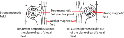
Neutral point
This is a region of space where two magnetic fields of equal magnitude and opposite direction cancel out. A magnetic dipole (compass needle) experiences zero magnetic force at this point.
Magnetic flux density, B
Magnetic flux density (B) is defined as the force acting per unit current per unit length on a wire placed at right angle to the magnetic field.
The S.I unit of B is tesla (T)
A tesla is the magnetic flux density in which a straight conductor of length 1m placed across the field and carrying a current of one ampere experiences a magnetic force of one Newton (1N)

Magnetic flux, φ (phi)
Magnetic flux, φ, is a measure of the number of magnetic lines passing normally across a given area of space. The strength of the magnetic field around a magnet depends on the number of lines per unit area.
Magnetic flux is thus, a product of magnitude of magnetic flux density and area of projection normal to magnetic field lines
I.e. φ = B x A = BA
S.I unit of magnetic flux φ is Weber (Wb)
If a magnetic field is at an angle, θ, to the area, A, then
φ = BAcosθ
A conductor carrying a current I placed in a magnetic field due to some source other than itself, experiences a mechanical force.
Demonstration of a magnetic force on a current carrying conductor

A short brass rod R is connected across a pair of brass rails, as shown in above.
A horseshoe magnet is placed so that the rod lies in the field between its poles.
When current passes through the rod, from an accumulator, the rod rolls along the rails, the direction of rolling is predicted by Fleming’s Left Hand rule.
Fleming’s Left Hand rule
States that when a straight conductor is placed across a magnetic field and a current is passed through it, the direction of magnetic force is predicted by the thumb when the first two fingers are placed perpendicular to each other. The first finger pointing in magnetic field direction and the second finger in the direction of current.
 .
.
Explanation for the origin of the force

- The current in the conductor produces a magnetic field around it.
- This magnetic field of the current carrying conductor interacts with the magnetic field of the magnet.
- This creates a region of stronger magnetic field on one side of the wire and a weaker magnetic field on the opposite side.
- A net force F = BIL then pushes the wire/conductor from the direction of stronger field to that of weaker field as shown above.
Factors affecting the magnitude of force experienced by a current carrying conductor placed across a magnetic field
(i) Magnetic field strength or flux density, B; magnetic force increases with magnetic field density.
(ii)Size of current, I, flowing through the conductor; the force is directly proportional to the current.
(iii) Length L of the conductor; the force is directly proportional to the length of the conductor.
(iv) Angle of inclination of conductor across a magnetic field
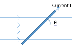
F = BILsinθ
When θ =900; F = BIL
When θ = 0; F = 0
It follows that F is zero when the conductor is parallel to the field direction
Magnetic Permeability
Magnetic Permeability is the ability of the material to form an internal magnetic field within itself under the influence of an applied magnetic field.
Or
Magnetic permeability is the ability of a material to become magnetized when exposed to a magnetic field.
The SI unit of magnetic permeability is Henry per meter.
The main application of magnetic permeability is the characterization of magnetic materials such as paramagnetic, diamagnetic or ferromagnetic.
Electromagnets, transformers, and inductors use materials with significantly high magnetic permeability values.
Factors Affecting Magnetic Permeability
Magnetic permeability depends on the nature of the material, humidity, position in the medium, temperature, and frequency of the applied force.
Magnetic Permeability Formula
Magnetic permeability formula is given as;
Magnetic permeability (μ) = B/H
Where B = magnetic intensity and H = magnetizing field.
The SI unit of magnetic permeability is henneries per meter (H/m) or Newton per ampere squared (N⋅A−2).
Types of Permeability
The different types of permeability include;
- Permeability of Free Space, air or vacuum.
It is represented by μ0=B0/H
The ratio of magnetic intensity in a vacuum and magnetizing field.
- Permeability of Medium
The ratio of magnetic intensity in the medium and magnetizing field.
It is expressed as;
μ = B/H
- Relative Permeability =

Calculation of magnetic flux density due to a current in straight wire conductor, a solenoid and a plane circular coil
(a) The magnetic field density, B for a point at distance, d, perpendicular to a straight wire carrying a current I in a medium of permeability, μ is obtained as follows.

Example 2
Use the diagram below, write down the expression for magnetic flux density at P due to current in a straight wire conductor AB in the vacuum.

(b) The magnetic flux density experienced at the centre, along the axis and at the ends of a solenoid of length (L), number of turn (N), and carrying a current (I) is calculated from

(c) The magnetic flux density B at the center of a plane circular coil of radius, r, and having N-turns of wire each carrying current I in the vacuum.

Example 4
Determine the magnetic flux density at the center of plane circular coil of 10 turns each, radius r and currying a current I in a vacuum.

Example 5
A plane circular coil of 20 turns is placed with its surface flat on a horizontal table. If the plane of the coil is threaded by magnetic field of flux density 3.6 x 10⁻⁵T at an angle 670, find magnetic flux threading the coil of radius 5cm

Magnetic flux threading the plane of the coil normally
φ = B’A where B’ = Bsin 670
= BAsin 670
= Bπr2sin670
= 3.6 x 10⁻⁵ x π x (0.05)2 x sin670
= 2.6 x 10⁻⁷Wb
Magnetic flux density due to a solenoid (long coil) carrying a current I
Derivation of F = BIL
(a) Derivation of an expression of attractive force, F, between two parallel wires carrying currents I1 and I2 in the same direction
Let F1 = B2I1L be the perpendicular attractive force wire 1 experiences due to magnetic field of wire 2 and F2 = B1I2L be the perpendicular attractive force experienced by wire 2 due to magnetic field of wire 1


Derivation of an expression of repulsive force, F, between two parallel wires carrying currents I1 and I2 in the opposite direction
Let F1 = B2I1L be the perpendicular repulsive force wire 1 experiences due to magnetic field of wire 2 and F2 = B1I2L be the perpendicular repulsive force experienced by wire 2 due to magnetic field of wire 1

Generally, F1 = F2 = F
When current is flowing in the same direction, the forces between the wires are attractive but in different directions, the forces are repulsive.
Ampere
It is a unit of current.
Definition
An ampere is a steady current which when flowing in each of two straight parallel wires of infinite length and negligible cross section area and placed a distance of 1m apart in a vacuum produce a force of 2 x10⁻⁷N per meter on each other.
Derivation of an ampere

Example 5
Two straight wires A and B carry currents 4A and 6A respectively in a vacuum. Given that A and B are parallel to each other and are a distance of 2.0cm apart, calculate the resultant magnetic field mid-way between the wires carrying current in
(a) Opposite direction
Solution

(b) Same direction

Example 7
Find the force per unit length of the wires when IA = 8.0A, IB =11.0A and r = 3.0cm (04marks)
The magnetic flux density which A produces at B is given by

Example 8
Two parallel wires P and Q, each of length 0.2m carry currents of 10A and 1A respectively

The distance between the wires is 0.04m. If both wires remain stationary and the angle of the plane with the horizontal is 300. Calculate weight of Q.
Solution


Example 9
Two parallel wires, P and Q of equal length 0.1m, each carrying a current of 10A are a distance 0.05m apart with P directly above Q. If P remains stationary, find the weight of P. (03marks)
Solution
Force due to magnetic field on P = weight of P, W.

Example 10
Two straight long and straight wires of negligible cross-section area carry currents of 6.0A and 3.0A in opposite direction as shown below

If the wires are separated by a distance of 8.0cm, find the
(i) Magnetic flux density at a point mid-way between the wires (04marks)
Solution

(ii) Force per meter between the wire (03marks)

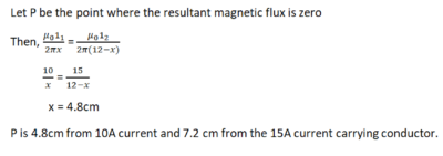
Example 11
Two long parallel wires placed 12cm apart in air carry currents of 10A and 15A respectively in the same direction. Determine the position where the magnetic flux is zero. (04marks)

Measurements of current using a current balance
Measurements of current using a current balance
The ampere balance (also current balance or Kelvin balance) is an electromechanical apparatus used for the precise measurement of the SI unit of Electrical current, the ampere. It was invented by Williams Thomson 1St Baron Kelvin.
Set up
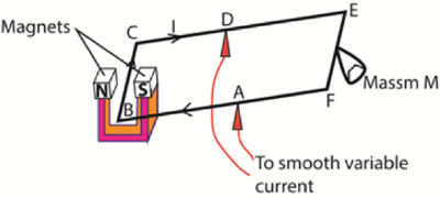
AB = AF, length BC = L and the current through the wire is A
The magnets provide a uniform magnetic field, B, perpendicular to wire BC.
At equilibrium when the frame BCEF is balanced
The force exerted on the wire = weight of the mass
BIL = Mg

Sources of error
- Accuracy of length L
- Rigidity of the frame
- To avoid overheating, the current should be switched off as soon as measurements have been taken.
- Shield the set-up from the disturbance of wind.
Magnetic induction
This is the process by which a magnetic substance acquires magnetic properties temporarily due to the presence of a magnet close to it. For instance, when a magnet is placed close to an iron piece without touching it, the iron piece behaves like a magnet.
Types of electromagnetic induction
Motional induction is the generation of an electromotive force (emf) in a conductor when it moves through a magnetic field.
Transformer induction involves the transfer of energy between two or more coils through changing magnetic field.
Self-induction
It is a process by which an e.m.f is induced in a coil or circuit when the magnetic flux linking it changes due to the current flowing in the same circuit/coil.
Experiment to demonstrate self-induction
The circuit is arranged as shown below.

Procedure
- Switch K first closed and the rheostat adjusted until the two bulbs indicate the same brightness.
- When the switch is opened and closed again, bulb A2 is observed to attain maximum brightness almost instantly while bulb A1 take some time to attain maximum brightness.
Explanation
The current in A1 takes some time to attain a steady value due to back e.m.f induced in the coil as a result of change in the current flowing (due to self-induction) in the coil when the switch is closed.
The back e.m.f gradually decay to zero as current establishes a steady value and hence the current in the coil rises slowly to its maximum when the back e.m.f is zero for there is no change in magnetic flux linking it.
Example 12
In the figure below, A and B are identical bulbs and L is an iron cored coil.

(i) Explain what will be observed when switch K is closed and when it is opened
When K is closed, bulb A light s dimly and slowly becomes brighter while B becomes bright almost instantly and later the two bulbs acquire the same brightness.
When K is closed, the current begins to flow around the closed circuit and gradually increases to its steady value or maximum. The sudden change or increase in the current creates an increase in the magnetic flux around the coil and large back e.m.f is induced into the coil due to self-induction. This greatly oppose the flow of current in bulb A, causing most of the current to flow in bulb B, hence bulb A lights dimly and B brighter initially but latter the back e.m.f decay to zero and bulbs A and B now light to the same brightness.
When the switch is opened, bulbs A and B dim out gradually before going off. This is because opening switch will cause the currents and hence the magnetic flux around the coil to decay to zero. This cause back e.m.f in the opposite direction which tries to maintain the current in the circuit and hence the bulbs dim out gradually.
(ii) Explain what you would observe when a battery is replaced by a.c voltage source and K is closed.
Bulb A may not light while B lights brightly because a.c causes a higher constant rate of change in magnetic flux around the soft iron cored coil and hence back e.m.f is constantly induced in the coil which greatly opposes the flow of current in A. The current in A may not rise to a value enough to lit it.
Secondary observation
The iron core become warm
- The higher constant rate of change in magnetic flux induces eddy currents in the core which generate heat by I2R mechanism.
- The a.c causes the direction of the magnetic domain in iron core to change according to the changing flux. This requires energy (hysteresis) which is later converted into heat energy in the core
Mutual induction
It is a process by which an e.m.f is induced in a coil when the magnetic flux linking it changes as a result of a change in the current flowing in nearby coil.
Experiment to demonstrate mutual induction

- The setup is shown above, coil A is place close to coil B but not touching.
- When the switch K is closed, the galvanometer deflects indicating induction of e.m.f in the coil B, hence mutual induction.
Self-inductance
This is the tendency of a coil to resist changes in current itself. Whenever current changes through a coil, they induce an emf, E which is proportional to the rate of change through the coil.

It can also be defined as the ratio of the magnitude of the back e.m.f induced in a coil or circuit to the rate of change of current flowing in the coil or circuit.
Or
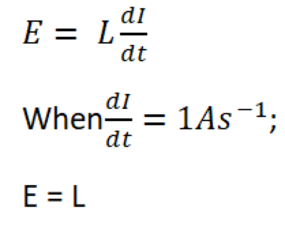
Thus, self-inductance can also be defined as the magnitude of the back e.m.f induced in a coil or circuit when rate of change of current flowing in the coil is 1As-1.
Magnetic flux, φ
Magnetic flux density is the force acting on a charge of 1C moving with a velocity of 1ms-1 at right angle to magnetic field.
Or
Magnetic flux is a vector whose magnitude is equal to the product of the area of the plane of the conductor or coil and the component of magnetic flux density normal to the plane of conductor or coil.

For a coil of N turns, magnetic flux linkage
Φ =NBAcosθ
Experiments to measure magnetic flux density
(a) An experiment to determine the magnetic flux density of a uniform magnetic field using a search coil and ballistic galvanometer

A search coil of cross section area A and number of turn’s N is connected in series with ballistic galvanometer. The search coil is then placed in uniform magnetic field such that the plane of the coil is perpendicular to the magnetic field. The coil is then pulled completely out of the field. The first deflection of the ballistic galvanometer noted θ1.
A capacitor of known capacitance C is then charged to a p.d. V and then charged through the ballistic galvanometer, θ2 is noted
The magnetic flux density of uniform magnetic field is obtained from

Where R is the resistance of the whole circuit.
(b) An experiment to measure the magnetic flux density between the poles of pieces of a strong magnet.

A search coil is connected to a ballistic galvanometer. The coil is then placed with its plane normal to the magnetic field whose magnetic flux density, B is required.
The coil is then pulled completely out of the field and deflection θ1 of ballistic galvanometer is noted

A capacitor of known capacitance Q is charged to a p.d. V and is then discharged through the ballistic galvanometer. The deflection θ2 is noted
CV = Cθ2
The magnetic flux density B is now calculated from

where A is the area of the coil,
N is the number of turns in the coil and
R is the resistance of the coil circuit.
(c) An experiment to determine the value of the earth’s magnetic flux density at a place, using a search coil.

- A coil of known number of turns, N (about 100) and area A is connected to a calibrated ballistic galvanometer so that the total resistance in the circuit is R.
- The coil is placed in a vertical plane perpendicular to the magnetic meridian of the earth as shown in (i) in figure above. The coil is then rotated through 1800 about the vertical axis. The maximum throw θ1 is noted.
- The coil is then placed with its plane in horizontal plane perpendicular to the magnetic meridian of the earth as shown in (ii) in figure above. The coil is then rotated through 1800 about the horizontal axis. The maximum throw θ2 is noted.
- Treatment of results

k is obtained by charging standard capacitor to a known p.d V and then discharging it through the ballistic galvanometer and the deflection α is noted.

Magnetic moment
Magnetic moment, also known as magnetic dipole moment, is the measure of the object’s tendency to align with a magnetic field.
Magnetic Moment is defined as magnetic strength and orientation of a magnet or other object that produces a magnetic field.
The magnetic moment is a vector quantity. Magnetic moments of two magnets are compared using a deflected magnetometer.
The structure and mode of action of the deflection magnetometer
The structure and mode of action of the deflection magnetometer
It consists of a small compass needle (small magnet) enclosed in a transparent box which is pivoted on a vertical axis and carries alight aluminium pointer. The pointer can rotate over a circular scale.
The box is fixed in the center of wooden box with two arms of linear scales of 0.5m each that coincide at the center of the magnetic compass.
Deflection magnetometer is used for
- Comparing magnetic moments of two magnets
- Verifying inverse law
The magnetometer can be used in two position; i.e. Tan A position and Tan B position

- Tan A position
The arms of magnetometer are adjusted to be parallel the aluminium pointer so that they lie in east-west direction and compass pointer adjusted to read zero degrees on the circular scale while the magnetic needle lies in the direction of magnetic meridian
- Tan B position
The arms of magnetometer are adjusted to be parallel the aluminium pointer so that they lie in north-south direction and compass pointer adjusted to read zero degrees on the circular scale while the magnetic needle lies in the direction of magnetic meridian
Comparing magnetic moments of two magnets using a magnetometer at equal distances in Tan A position

(a) The first bar magnet is placed a distance d from the magnetic compass as shown above and angles of deflection of aluminium pointer α1 and α2 are noted
(b) The polarity of the bar magnet in (a) is reversed and angles of deflections α3 and α4 are noted
(c) The first bar magnet is placed equal distance d from magnetic compass on the opposite arm and angles of deflection of aluminium pointer α5 and α6 are noted
(d) The polarity of the bar magnet in (c) is reversed and angles of deflections α7 and α8 are noted
(e) Average angle
![]()
(f) Steps (a) to (e) are repeated for the second magnet to obtain average angle θ2
(g) The ratio of magnetic moments is given by
![]()
Comparing magnetic moments of two magnets using a magnetometer at equal distances in Tan B position

(a) The first bar magnet is placed a distance d from the magnetic compass as shown above and angles of deflection of aluminium pointer α1 and α2 are noted
(b) The polarity of the bar magnet in (a) is reversed and angles of deflections α3 and α4 are noted
(c) The first bar magnet is placed equal distance d from magnetic compass on the opposite arm and angles of deflection of aluminium pointer α5 and α6 are noted
(d) The polarity of the bar magnet in (c) is reversed and angles of deflections α7 and α8 are noted
(e) Average angle
![]()
(f) Steps (a) to (e) are repeated for the second magnet to obtain average angle θ2
(g) The ratio of magnetic moments is given by
![]()
Comparing magnetic moments of two magnets using a magnetometer and null method in tan A position

(a) Place one magnet a distance d from the magnetic compass and another on the opposite arm facing each other.
(b) Adjust the second magnet to a distance r1 until the compass needle shows zero deflection
(c) Reverse the poles of the two magnets keeping the distance d of the first magnet and determine the distance r2 of the second magnet leading to zero to zero deflection.
(d) The magnets are interchanged keeping the distance d of first magnet unchanged, procedures (b) and (c) are repeated for distances r3 and r4.
(e) Now
![]()
(f) The ratio of magnetic moments is given by
![]()
Comparing magnetic moments of two magnets using a magnetometer and null method in tan B position
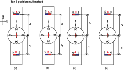
(a) Place one magnet a distance d from the magnetic compass and another on the opposite arm facing each other.
(b) Adjust the second magnet to a distance r1 until the compass needle shows zero deflection
(c) Reverse the poles of the two magnets keeping the distance d of the first magnet and determine the distance r2 of the second magnet leading to zero to zero deflection.
(d) The magnets are interchanged keeping the distance d of first magnet unchanged, procedures (b) and (c) are repeated for distances r3 and r4.
(e) Now
![]()
(f) The ratio of magnetic moments is given by
![]()
Verifying inverse square law with deflection magnetometer
A. Arrange the magnetometer in tan A position
(a) The first bar magnet is placed a distance d from the magnetic compass as shown above and angles of deflection of aluminium pointer α1 and α2 are noted
(b) The polarity of the bar magnet in (a) is reversed and angles of deflections α3 and α4 are noted
(c) The first bar magnet is placed equal distance d from magnetic compass on the opposite arm and angles of deflection of aluminium pointer α5 and α6 are noted
(d) The polarity of the bar magnet in (c) is reversed and angles of deflections α7 and α8 are noted
(e) Average angle
![]()
B. Arrange the magnetometer in tan B position
(a) The first bar magnet is placed a distance d from the magnetic compass as shown above and angles of deflection of aluminium pointer α1 and α2 are noted
(b) The polarity of the bar magnet in (a) is reversed and angles of deflections α3 and α4 are noted
(c) The first bar magnet is placed equal distance d from magnetic compass on the opposite arm and angles of deflection of aluminium pointer α5 and α6 are noted
(d) The polarity of the bar magnet in (c) is reversed and angles of deflections α7 and α8 are noted
(e) Average angle
![]()
(f) Inverse square law is verified if
![]()
Electromagnetic induction
It is the induction of an e.m.f. in a conductor or in a coil by moving it relatively to a magnetic field
Laws of electromagnetic induction
- Faraday’s law states that the magnitude of the e.m.f induced in a circuit is directly proportional to the rate of change of magnetic flux linked with the circuit.
- Lenz’s Laws states that induced current flows always in such a direction as to oppose the change which is giving rise to it.
An experiment to demonstrate Faraday’s law of electromagnetic induction.
Verification setup

X and Y are brush contact.
A copper rod which can rotate round the north pole of permanent magnet is connected as shown above.
The wheel is turned steadily until the deflection of the galvanometer is constant.
The time, t, for N rotations is measured and the number of revolution (n) per second is determined from n =N/t . The deflection θ of the galvanometer is also noted.
The experiment is repeated at different speed of rotation of the wheel and values of n and θ tabulated.
A graph of θ against n is plotted.
A straight line graph is obtained implying that θ n
Since θ is proportional e.m.f induced and n proportional to speed of rotation of the rod, then the induced e.m.f is proportional to the rate of change of flux linkage.
An experiment to illustrate Lenz’s law of electromagnetic induction

- The galvanometer is first connected in series with a battery and the direction for a given direction of current is determined.
- The battery is disconnected and is replaced by a coil of known winds.
- A strong permanent magnet is brought towards the coil with N-pole facing the coil, the galvanometer deflects in a direction for which the side of the coil facing the magnet is N-pole.
- When the magnet is move away from the coil, the galvanometer deflects in opposite direction, implying that the pole near the coil is an S-pole.
- In the first case, the pole due to the induced current was repelling the approaching magnet, while in the second case, the pole was attracting the receding magnet.
- The induced current therefore is in such as to oppose the change causing it, which is Lenz’s law.
Example 12
Explain why Lenz’s law is referred to as an example of energy conservation or
Why Lenz’s law does not violet the principle of conservation of energy.
In order not to violet the principle of conservation of energy, the effects of induced current must oppose the motion of the magnet in such a way that work done by an external agent in moving the magnet is the one that is converted into electrical energy and hence there is just transformation of energy from one form to another (from mechanical energy to electrical energy) and hence Lenz’s law is an example of energy conservation..
Magnitude of e.m.f induced in a coil depends on
- Number of turns N in the coil
- Rate of change in magnetic flux
- Strength of Magnetic flux
- Area of the coil
Magnetic moment of a coil.
Magnetic moment is torque experienced by the coil per tesla of magnetic field acting along the plane of the coil.
Or
Magnetic moment of a coil is a couple exerted on a coil when it is placed with its plane parallel to a magnetic field of 1T
Magnitude of e.m.f induced in a coil depends on
Number of turns N in the coil
Rate of change in magnetic flux
Strength of Magnetic flux
Area of the coil
Magnetic moment of a coil
Magnetic moment is torque experienced by the coil per tesla of magnetic field acting along the plane of the coil.
Or
Magnetic moment of a coil is a couple exerted on a coil when it is placed with its plane parallel to a magnetic field of 1T
Derivation of expression for torque on rectangular coil in a magnetic field
Consider a rectangular coil of N turns each of dimensions a x b inclined at an angle α to uniform magnetic field of flux density, B.
- When current, I, flows through the coil, the conductor experiences a magnetic force.
- Force on side PQ = NBIbsinα (downwards) while Force on side RS = NBIbsinsα (upwards). The two forces cancel out due to rigidity of the coil.
- Side PS experiences force NBIacosα perpendicularly into the page while RQ experiences force NBIacosα perpendicularly out of page. The two forces constitute a couple whose moment of force
Example 13
A small circular coil of 20 turns of wire lies in a uniform magnetic field of flux density 5.0 x 10⁻²T. The normal to the coil makes an angle of 300 with the direction of the magnetic field. If the radius of the coil is 4cm and the coil carries a current of 2.0A, find the
(i) Magnetic moment of the coil (02marks)
M = NIA = 20π x (4 x 10-2)2 x 2 = 0.2Am2
(ii) Torque on the coil
T = MBsinθ = 0.2 x 5 x 10-2sin300 = 5.0x 10⁻³Nm
Example 14
Show that when the magnetic flux linking a coil changes, the total charge which passes through is depends only on the resistance of the coil and total flux linking it (05marks).
Solution
Consider a coil of N turns each linked by magnetic flux of φ1.
Suppose the magnetic flux changes to φ2.
When the magnetic flux φ changes, an e.m.f ε is induced in the coil.
Solution

The amount of the charge which passes through the coil when the magnetic flux changes from φ1 to φ2 is

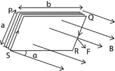
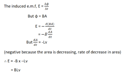
Derivation of e.m.f induced in a moving rod across a magnetic field
(a) Derivation of e.m.f induced in a moving rod by applying the laws of electromagnetic induction
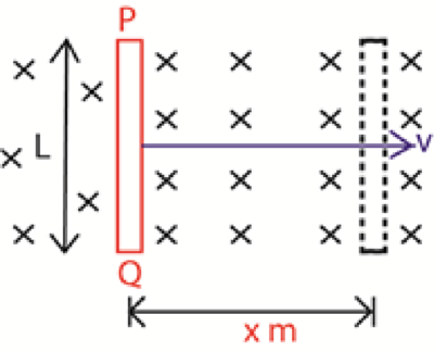
Considering a rod of length L meters moving at right angles to a uniform magnetic field of flux density B tesla moving with uniform speed v ms-1 as shown in figure below:

(b) Derivation of e.m.f induced in a moving rod by considering the force extended on the electrons
By virtue of motion of the rod in the magnetic field, the electrons inside the rod experiences a magnetic force.
Applying Fleming’s right Handle Rule, the induced e.m.f for current is directly from Q to P.
The electrons flow or drift from P to Q (by convention current and electrons flow in opposite directions) thus P acquires a positive charge and Q acquires a negative charge.
An electric field is thus setup which attracts electrons towards the positively charged end P.
Equilibrium is reached when upward electronic force is counterbalanced by the downward magnetic force.

(c) Derivation of e.m.f induced in a moving rod by applying the principle of conservation of energy
Consider a rod PQ placed at right angles to a uniform magnetic field of flux density B Tesla as shown.
Suppose the rod is moved through of x meters in time t seconds; from the principle of conservation of energy, work done by the external agent in moving the rod is what is conserved into electrical energy.
Therefore, electrical energy = work done in moving the rod.
If E is the induced e.m.f in the rod, then
EIt = Force x distance
But force = BIL, I is the induced current in the rod

Example 15
A rod PQ, 1.2m long moves at right angles to a magnetic field of flux density 0.4T and at a speed of 4ms-1. Find the e.m.f induced in the rod.
Solution
Induced e.m.f, E = BLv = 0.4 x 1.2 x 4 = 1.92V
Example 16

In the figure above, a rod PQ 1.2m long is moved in a perpendicular magnetic field of flux density 0.4T at a speed of 4m/s along a frictionless rails XY and WZ. Find the power generated by the rod.
Solution
Applying Fleming’s Right-Hand rule, the induced current flows from Q to P, this gives the polarity of induced e.m.f with a positive terminal on the side P.


E.m.f induced in a circular disc (disc dynamo)
A disc is an arrangement of obtaining electrical energy from mechanical energy by rotating a circular metal disc in a perpendicular magnetic field abut an axle passing through its center.

The disc is rotated at uniform angular velocity, ω, and the e.m.f induced in the disc is tapped by connecting a wire between the center of the disc axle and the rim of the disc.
The induced e.m.f is due to the motion of linear conductor of length = radius r.
From the e.m.f induced in a moving rod
E = BLv …………………………………….(i)
Where v is the average velocity,

Example 17
A circular metal disc of radius 8cm is rotated at right angle to a uniform magnetic field of flux density 0.4T at 80 revolutions per minute. Find the e.m.f induced in the disc.
Solution

Example 18
A circular metal disc of radius 12cm is rotated in a perpendicular magnetic field of flux density 0.4T about an axle of radius 6cm at 52rev/min. Calculate the e.m.f generated
Solution
Induced e.m.f, E = BAf

Example 19
A conducting disc of radius 0.05m with its plane perpendicular to uniform magnetic field of flux density 0.25T, rotates at 15 revolution per second about an axis through its center and perpendicular to its plane.
Calculate
(i) Magnetic flux threading the disc at any time (03marks)
Magnetic flux, φ = BA but A = πr2
=> φ = Bπr2
= 0.25 x 3.14 x (0.05)2 = 1.96 x 10⁻³Wb
(ii) e.m.f generated between the center of the disc and any point on its rim.
or ε = φf = 1.96 x 10-3 x 15 =2.9 x 10⁻²V
or ε = φf = 1.96 x 10-3 x 15 =2.9 x 10⁻²V
Example 20
An aero plane of wingspan 30m flies horizontally at a speed of 1000kmh-1.
What is the p.d across the tips of its wings, if the horizontal component of the earth’s magnetic field is 1.46 x 10⁻⁴T? (Angle of dip at the place is 700) (03marks)
E = BVLv; but Bv = BHtan700
E = BHtan700Lv
![]()
Example 21
A circular metal disc of radius R. rotates in an anticlockwise direction at angular velocity, ω, in a uniform magnetic field of flux density, B, directed into paper as shown in the figure below

Absolute method of measurement of resistance (Lorentz method)
The e.m.f induced in a moving rod is used in the absolute measurement.
A circular metal disc is placed inside a solenoid X of known number of turns, N and length, L meters in series with a battery, unknown resistance R, a rheostat and a switch K

Switch K is closed and the disc of diameter, r, is rotated about an axle passing through its center at such a speed until the e.m.f induced between the center and the rim is counter balanced by the potential difference across the resistor when the galvanometer shows no deflection
At this stage, the number of revolutions n in a given time t (s) are noted.
f = n/t (revolution per second)
area A of the disc =πr2
At no deflection the induced e.m.f in the disc, BAf = IR, where I is the current flowing through the coil

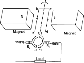
The simple a.c generator

It consists of a rectangular coil of wire pivoted between opposite curved poles of a strong magnet and free to rotate about its axis with uniform angular velocity.
The ends of the coil are connected to two slip rings which press slightly against the carbon brushes connected to the load.
How a generator works
- The coil ABCD is rotated in a magnetic field, the magnetic field linked with it changes and hence e.m.f is led away by means of slip rings which press slightly against the carbon brushes.
- Applying Fleming’s right hand rule, the induced current enters the coil AB and leaves the coil via CD.
- Starting with the coil in the vertical position, the magnetic flux linking it is maximum and hence no induced e.m.f.
- The induced e.m.f increases with the position of the coil in the magnetic field until it becomes maximum with the coil in horizontal position and then decrease to zero as the coil rotates to the vertical position
- The force acting on the sides of the coil change as the coil passes over the position and hence, the current flowing in the coil reverses. Hence an alternating e.m.f or current flows through the load.
A graph of induced e.m.f against time in an a.c generator

The main energy losses in an a.c. generator and how they are minimized
- Eddy current loss are minimized by laminating the armature
- I2R losses are minimized by use of low resistance winding wires
- loss due to friction minimized by lubricating the rubbing parts
d.c. generator
It consists of a rectangular coil abcd of wire pivoted between curved poles of a strong magnet and free to rotate about its axis with a uniform velocity.
The ends of the coil are connected to two halves of split ring (commutators) which press lightly against the carbon brushes connected to the load.
Mode of action
When the coil rotates at uniform velocity in magnetic field, e.m.f is induced in it. When the coil is in vertical position, the commutators change brushes C1 to B2 and C2 to B1.
E.m.f reverses direction but the current does not change direction. Hence current flows in the same direction in a resistor.
A graph of induced e.m.f against time in a d.c generator

The peak value of induced e.m.f increases with increase in
- The number of turns in the coil
- The area of the coil
- The strength of the magnetic field
- The frequency of rotation of the coil
How to convert a d.c generator be converted into an a.c generator.
To convert a d.c generator to an a.c generator, the ends of the rectangular coil are connected to a pair of slip rings instead of the commutators.
How to convert an a.c generator be converted into d.c generator
To convert an a.c generator to d.c generator, the ends of the rectangular coil are connected to a pair of commutators instead of the slip rings.
A d.c motor

It consists of a rectangular coil abcd of wire pivoted between curved poles of a strong magnet and free to rotate about its axis with a uniform velocity.
The ends of the coil are connected to two halves of sprit ring (commutators) which press lightly against the carbon brush.
Mode of operation
It consists of a rectangular coil abcd of wire pivoted between curved poles of a strong magnet and free to rotate about its axis with a uniform velocity.
The ends of the coil are connected to two halves of sprit ring (commutators) which press lightly against the carbon brushes.
Mode of operation
The switch K is closed and current flows in the coil in the direction shown
Applying Fleming’s left hand rule, ab experiences an upward force and side cd a downward force. the two forces constitute a couple which rotates the coil in a clockwise direction.
When the coil passes over the vertical position, the commutators change contact with the carbon brushes and current in the coil is immediately reversed. The forces acting on the sides thus change and the coil continues to rotate in the same direction.
Because the conductors cut the magnetic field, an e.m.f that oppose the supply voltage is induced in it called back e.m.f
If Vis the supply voltage and E is the back e.m.f, then then the current I is given by
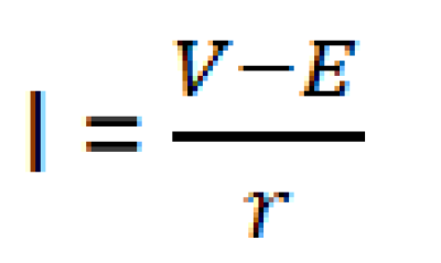 where r is the armature resistance
Back e.m.f and efficiency of the motor
When the armature coil of a motor rotates in magnetic field, an, e.m.f is induced in the coil. The induced e.m.f opposes the applied p.d. and is therefore a back e.m.f.
If V, E and r are applied p.d, induced e.m.f and resistance to the armature coil respectively, then the current flowing in the coil is given by
=> V- E = Ir
Multiplying through by I
VI = EI + I2r
Since I2r is the power dissipated as heat in the armature, EI is the mechanical power output and VI is the power supplied.

Example 24
A motor whose armature resistance is 2Ω is operated on 240V mains supply. If the back e.m.f in the motor is 220V, calculate the armature current. (03marks)

Example 25
A transformer has 2000 turns in the primary coil. The primary coil is connected to a 240V mains. A 12 V, 36W lap is connected to the secondary coil. If the efficiency of the transformer is 90%, determine the
(i) number of turns in the secondary coil (02marks)

(ii) current flowing in the primary coil (03marks)
IsVs = 0.9IpVp

Example 26
Explain the significance of back e.m.f. in the operation of a d.c. motor (02marks)
The back e.m.f in a d.c. motor provides the useful power of the motor.
back e.m.f also reduces the heating effect in motor by reducing the current, since
![]()
Difference between a d.c generator and d.c motor
A d.c. generator converts mechanical energy into electrical energy while a d.c motor converts electrical energy into mechanical energy
Moving coil galvanometer.

Structure
Structure
- It consist of a rectangular coil of fine insulated copper wire wound on an aluminium frame to provide electromagnetic damping.
- The coil together with the frame of aluminium are mounted over a soft iron cylindrical core and freely pivoted on jeweled bearing to minimize friction at contact.
- The suspension torsion wire suspending the coil is attached to a pair of control hair springs T1 and T2 for feeding current in and out of the coil and control rotation of the coil.
- The coil is then suspended between concave pieces of a strong magnet to provide magnetic field.
Mode of action
- Current I to be measured is passed into the coil via hair spring T1.
- The current then causes the coil to experience a deflection torque, τ = NABI due to a couple force causing rotation in a radial magnetic field.
- The coil turns with the pointer through angle θ until stopped by a restoring torque, τ = kθ provided by a pair of hair springs T1 and T2.
- At equilibrium, NABI = Kθ
![]()
I ∝ θ, hence the instrument has a linear scale
Where B = magnetic field strength between the poles of the magnets
A = area of the plane of the coil
N = number of turns of the coil
k = torsion constant of suspension spring
The factors which affect the current sensitivity of a moving coil galvanometer
- Strength of magnet, current sensitivity is proportional to the strength of the magnets
- Number of turns, current sensitivity is proportional to the number of turns
- Nature of suspension torsion wire, current sensitivity is inversely proportional to the torsion constant of the suspension torsion wire.
- Area A of the plane of the coil; current sensitivity is proportional to the area of the plane of the coil
- Size of copper wire making the coil; current sensitivity is proportional to the size of copper wires making the coil since the bigger the wires the lower the resistance.
Example 27
Explain why a moving coil ammeter cannot be used to measure alternating current from the mains. (03marks)
The coil rotates about a vertical axis between the north and south concave poles of strong magnets. These provide a radial magnetic field. When an alternating current is passed through the coil, the torque on the coil reverses direction at the same frequency as current. The pointer vibrates with very small amplitude about the mean position hence a steady current reading cannot be taken
Example 28
Explain why a moving coil galvanometer should have a radial magnetic field, fine springs and many turns. (06marks)
Radial magnetic field ensures that the Force, F, remains normal to the plane of the coil when it turns through an angle i.e.
Torque on the coil τ = BANIsinα, where α is the angle between the normal to the coil and magnetic field this is balanced by restoring torque = kθ due to current, where θ is the angle turned through

For a linear scale, sin α = 1 => radial field
For current sensitivity, k must be small, i.e. the springs must be fine
For current sensitivity, N, must be large
Other a.c measuring instruments
Thermocouple ammeter

P and Q are dissimilar wires
Current to be measured is passed through the wire AB and heats the junction R of the thermocouple. The thermoelectric effect generated at R causes a direct current to flow through the micrometer calibrated to measure the r.m.s value of current.
Example 29
Explain any precautionary measure taken in the design of thermocouple meter (02mark)
The fine wire is enclosed in an evacuated glass bulb to shield it from draughts. If the wire was in the open, some heat would be lost to the surrounding so that the temperature difference between the hot and cold junctions would not be proportional to the power dissipated in the wire.
The repulsion type moving iron meter.

- When a current is passed through the coil, the iron rods magnetize in the same poles adjacent to each other in whatever the direction of current. Hence they repel and the pointer moves in the same direction until it is stopped by the restoring spring.
- Since the magnetic force is proportional to the square of the average current, hence, the deflection is proportional to the square of average current.
- Advantage: it measured both direct and alternating current.
- Disadvantage: it has nonlinear scale
A hot wire ammeter.
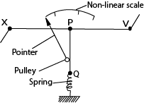
- The current flows through a fine resistance-wire XY, which it heats.
- The wire warms up to such a temperature that it loses heat-mainly by convection-at a rate equal to the average rate at which heat is developed in the wire.
- The rise in temperature of the wire makes it expand and sag; the sag is taken up by a second fine wire PQ, which is held taut by a spring.
- The wire PQ passes round a pulley attached to the pointer of the instrument, which rotates as the wire XY sags.
- The deflection of the pointer is roughly proportional to the average rate at which heat is developed in the wire XY; it is therefore roughly proportional to the average value of the square of the alternating current, and the scale is a square-law one.
The structure and action of a.c transformer.
![]()
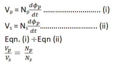
- Transformer consists of two coil of insulated wire, the primary and secondary wound on laminated soft iron core.
- When alternating voltage, Vp is connected to primary coil, it drives alternating current in the primary coil.
- The alternating current produces a varying magnetic flux φp that link the primary coils inducing a back e.m.f EB in the primary.
- The varying magnetic flux, φs links the secondary coil by mutual induction/inducing alternating voltage, Vs in the secondary
When Ns > Np the transformer is a step up
Ns < Np the transformer is a step down
Example 30
Explain why the voltage at a generating power station must be stepped up to very high value for long distance transmission (03marks)
Transmission is at high voltage to reduce power loss
Note that
Power supplied, P =IV
![]()
Hence when V is high, I is small. From power loss, P’ = I2R, when I is small power loss is reduced.
Example 31
A transformer connected to a.c supply of peak voltage 240V is to supply a peak voltage of 9.0V to a mini-lighting system of resistance 5Ω. Calculate the

Example 31
Explain why the current in the primary coil of a transformer increases when the secondary is connected to the load.
When load is connected to the secondary winding, a current flows in it. The current flows in such a direction as to reduce the back e.m.f in primary coil, hence the current increase
Energy losses in a transformer and how they are minimized
-
- Heat dissipated in the windings by I2R mechanism. This is minimized by use low resistance thick copper wires.
- Energy loss resulting from loss of flux or flux leakage. This is minimized by winding secondary coil on primary coil
- Eddy currents are minimized by laminating the core.
- loss due to friction minimized by lubricating the rubbing parts
- When an alternating current is passes through the coil, wound on the core, the magnetic domain dipoles are forced to change directions according to changing magnetic flux created as a result of a.c. These changes of the domain dipoles require energy which is lost from the system. This energy loss is called hysteresis loss.
Hysteresis loss is minimized by using a core made of self-magnetic substance which requires very little energy to create magnetic reversal e.g. soft iron below the hysteresis curve of a ferromagnetic substance
- A graph, explain the hysteresis curve for ferromagnetic material

- When a magnetic field is applied to a ferromagnetic material, the magnetic domains tend to align with the applied field. The magnetic flux density increases along OA until saturation. When the magnetizing field is reduced to zero, there is residue magnetization at C. This is due to failure of the dipoles to respond instantly. Energy is lost.
- To bring the dipoles to their original orientation, a magnetic field OD is applied in opposite direction. As the magnetic field is increased in this reversed direction, saturation is attained at E
- When reversed magnetic field is reduced to zero, state F is attained. Reversal of dipoles requires an increase of magnetic field in opposite direction to state EF. The cycle is then repeated on further increase of magnetic field
- The curve of B verses H is called a hysteresis curve
Uses of transformers
A transformer is used to step up or down voltage to suit the required appliance.
The appliances that may require a transformer include telephone, radios, loud speakers, x-ray machines. T.Vs and so on.
Eddy currents
If a block of metal is moved in a magnetic filed or kept in changing magnetic field, free electrons in the conductor experience a force and begin to circulate.
This gives rise to induced currents in a closed circular path known as edd currents.
These currents flow in such a direction so as to oppose the motion of a conductor in the field.
Eddy currents produce a large amounts of heat in the soft iron core of transformers, induction coils,electronics and thus reduce efficiency of electrical devices.
Uses of eddy currents
- Damp oscillations in a moving coil galvanometer preventing oscillation of the pointer and leading to accurate reading
- Eddy currents produce enough heat to melt metals in induction furnace.
- Electric brakes: the axle of a train is surrounded by a coaxial cylindrical drum. When the train is to be stopped, a strong magnetic field is applied to the rotating drum. This generates large eddy currents that oppose motion of axle.
- Speedometer, eddy current are used in speedometer
Sinusoidal a.c Currents

Terminologies
An alternating current or voltage
It is the voltage or current whose magnitude and direction varies periodically with time.
NB: Its variations with time can be represented by sine curve or wave and it is sometimes referred to as a sinusoidal current or voltage.
Example
What is meant by a sinusoidal voltage?
A sinusoidal voltage is a voltage whose variation with time can be represented by a sine curve.
Peak value/ amplitude
It is the maximum current or voltage of an alternating current.
NB: peak values are denoted by V0, Vm, I0. or Im.
Root mean squared value (r.m.s)
It is a steady current or voltage that would dissipate heat in a given resistor at the same rate as the alternative current or voltage.

Period, T
It is the time taken to complete one cycle
Frequency, f
It is the number of cycles per second

a.c wave equation
The sinusoidal wave equation for a.c are represented by
V = V0sin ωt and,
I = I0sinωt
Where I0 and V0 are the peak alternating current or voltage

∴ ω =2πf
Thus, the wave equations can be written as
V = V0sin 2πf t and,
I = I0sin2πf t
From Ohm’s law
V = IR
![]()

Example 33
A sinusoidal alternating voltage V = 170sin120πt, voltage, is applied across a resistor of resistance 100Ω
Determine

A capacitor in an a.c circuit
Assume a sinusoidal voltage
V = V0sinωt ……………………….. (i)
Across the capacitor plates from definition of capacitor.
The instantaneous charge Q on plates is
Q = CV……………………………… (ii)
Putting (i) into (ii)
Q = C V0sinωt ………………….. (iii)

Variation of V and I against time

Explanation of the curve

Reactance
This is the non-resistive opposition to the flow of alternating current in either a capacitor or an inductor.
Greater reactance leads to smaller currents for the same applied voltage. Reactance is similar to electric resistance, although it differs in several respects
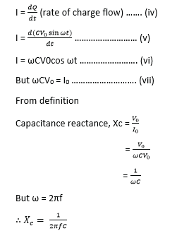
Reactance of a capacitor (capacitive reactance)
It’s denoted by Xc.

Derivation of an expression for reactance of a capacitor
Assume a sinusoidal voltage;
V = V0sin ωt ……………………… (i)
Across capacitor’s plates; the instantaneous charge Q is
Q =CV ……………………………… (ii)
Q= CV0sin ωt ………………….. (iii)
From definition of current,
Example 34
A sinusoidal voltage of r.ms value 13.2V is connected across a 50μF capacitor.
(i) Find peak value of the charge on the capacitor (02marks)
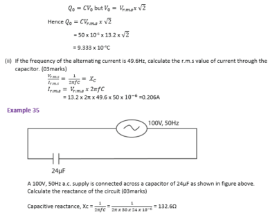
Example 36
A capacitor of capacitance 60μF is connected to an a.c. voltage supply of frequency 40Hz. An a.c ammeter connected in series with the capacitor reads 2.2A. Find the p.d across the capacitor. (03marks).

Example 37
A sinusoidal p.d of r.m.s value of 20V and frequency50Hz is applied across a 100μF capacitor. Calculate the capacitive reactance of the circuit. (02 marks)

a.c through an inductor
An inductor, also called a coil, choke, or reactor, is a passive two-terminal electrical component that stores energy in a magnetic field when electric current flows through it. An inductor typically consists of an insulated wire wound into a coil
Example of inductors

Example 38

(ii) Using the axes, sketch graphs to show the relative phases of the current and voltage across the inductor. (02marks)

Note that the current starts at zero and rises to its peak after the voltage that drives it, i.e., the voltage across an inductor leads the current because the Lenz’s Law behavior resists the build up of current and it takes a finite time for an imposed voltage to force the buildup of current to its maximum.
Derivation of an expression for reactance of an inductor

Ballistic galvanometer
It is also called a moving coil galvanometer used for estimating the quantity of charge flow whose deflection of the coil is directly proportional t0 the charge that passes through it.
Please download pdf: A-level physics Magnetism
Share with a friend
Your comments are highly welcome
Thank you so much
Very good
Thankyou so much
Good evening? I’m avaga kenjosh a S.5 student wish to sake for your help on some question banks of “A” level physics, economics and maths, please if possible drop them on my email
Thanks for the great initiative.could you have made notes on electricity so that you can avail me?
download free notes, tests, exams and marking guidesfor physics, chemistry, biology, mathematics, economics and geography from digitalteachers.co.ug, It is simpler after downloading digitalteachers.co.ug App. The trick in passing UNEB is to write and rewrite notes, questions and marking guides.
Thanks for magnificent info I was looking for this info for my mission.
Your insights always resonate with me. Car & Motorbike