
Modern physic A-level notes

Modern Physics (A-level)
Photoelectric effect
In metals, atoms exists as positive ions in a sea of electrons. An electron near the surface of the metal, say A, experiences an attractive inward force from the positive charges below it.

For such an electron to escape from the metal surface, a specific amount of work has to be done to overcome the forces which are inward.
Definitions
Photoelectric emission: this is the liberation of an electron from a metal surface by use of light of a suitable frequency.
Thermionic emission: this the liberation of an electron from a metal surface by application of heat.
N.B
– The light (radiation) supplies the electrons with an amount of energy equal or exceeding the energy that binds them to the surface.
– The liberated electrons are called photo electrons.
– Surfaces which are able to undergo electric emission are said to be photo emissive e.g. K, Na, Ca, etc. generally group I elements. These have low ionization energy or low work function
– The occurrence of photoelectric effect can be demonstrated by using a gold leaf electroscope and a suitable metal e.g. zinc.
Laws of photoelectric emission
The laws (characteristics or features) are just a summary of experimental results on photoelectric effect.
- The time lag between irradiation of the metal surface and emission of the electrons by the metal surface is negligible.
- For a given metal, surface there is a minimum value of frequency of radiation called threshold frequency (f0) below which no photo electrons are emitted from the metal however intense the incident radiation may be.
- The number of photoelectrons emitted from the surface per second is directly proportional to the intensity of incident radiation for a particular incident frequency
- The K.E of the photoelectrons emitted is independent of the intensity of the incident radiation but depends only on its frequency
A simple experiment to demonstrate Photo electric effect
A freshly cleaned Zinc plate is connected to the cap of a negatively charged gold leaf electroscope.
Ultra violet radiations are allowed to fall on the zinc plate

Observations
- The leaf of the electroscope gradually falls
- This shows that both the zinc plate and the electroscope have lost charges.
- The lost charges are found to be electrons, hence photoelectric effect has occurred.
Note:
If a positively charged electroscope is used instead, there is no observable change in the divergence of the leaf because the emitted electrons are immediately attracted back by the positive charges on the cap of the electroscope hence restoring the charges.
Planks Quantum theory
States that the energy /radiation emitted or absorbed is discrete or in packets called quanta. That’s, we can have integral values such as 1, 2, 3 … n, but not fractional amount of energy
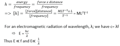
The energy E, contained in a quantum of radiation is proportional to the frequency f, of the radiation i.e. E E =hf where h = Planks constant (6.626 x 10– 34Js)
Dimensions of h
The quantum theory of photoelectric effect
– Light energy is emitted and absorbed in discrete packets of energy called photons.
– Each photon carries (or delivers) a packet of energy or quanta given by hf. Where f is the frequency of the light/radiation and h is Plank’s constant.
– It is the photon that knocks off electrons from the metal surface.
– When the photon (of energy = hf) collides with an electron, it is either
a) Reflected with no change in its energy or
b) Absorbed by the electron and the photon gives up all its energy to that single electron without sharing with other electrons
– To liberate/eject an electron from a particular metal surface, a quantity of energy called work function, wo (which is characteristic of the metal) has to be supplied by the incident radiation
Thus a photon of energy E, (hf) causes an electron to be emitted from the metal surface
If the energy E, (hf) is greater than the work function (wo) of the metal, the excess energy (hf – wo) is absorbed as the K.E of the emitted electron or photoelectron
i.e. hf –wo = ½ mv2 where v is the velocity of emitted electron
or hf= w0 + ½ mv2 ; also called Einstein photo electric equation
The emitted electron escapes with a velocity having any value up to a maximum. The value of maximum velocity depends on:
The work function, wo of the metal and,
The frequency f of the incident radiation
From, hf –wo = ½ mv2
hf = energy of incident radiation of frequency, f
wo = work function of the metal. It is defined as the minimum amount of energy required to release an electron from a metal surface.
½mv2 = the maximum kinetic energy of the emitted electron
If a photon has just enough energy to liberate the electron, the emitted electron gains no kinetic energy and therefore floats on the surface of the metal.
Since the work function wo is constant for a particular metal, there exists a minimum frequency (threshold frequency, f0) given by wo = hf0
From, hf –w0 = ½ mv2
then h(f-f0) = ½ mv2

- If an electron of charge e is accelerated by a voltage V volts, it gains K.E given by K.E = eV.
Hence from above h(f – f0) = eV
- An electron volt (eV) is the K.E gained by an electron which has been accelerated through a p.d of one volt
- 1eV = 1.6 x 10⁻¹⁹J
- The values of the constants are h = 6.64 x 10⁻³⁴Js, c = 3.0 x 10⁸ms-1, e = 1.6 x 10 -19C
Definitions
Threshold wavelength is the maximum wavelength that is required to emit the electrons from a metal in the photo electric effect
Threshold frequency is the minimum frequency of incident radiation below which photoelectric emission cannot occur.
Example 1
Monochromatic radiation of frequency 1.0 x 10¹⁵ Hz is incident on a clean magnesium surface for which the work function is 0.59 x 10⁻¹⁸J. Calculate
(i) the maximum kinetic energy of the emitted electrons
kinetic energy = hf – w0
= 1 x1015 x 6.64 x 10-34 – 0.59 x 10⁻¹⁸J
= 7.4 x 10⁻²⁰J
(ii) the potential to which the magnesium surface must be raised to prevent the escape of electrons
potential energy = kinetic energy
eV = 1.04 x 10⁻¹⁹J
V = 7.4 x 10⁻²⁰J/1.6 x 10-19
= 0.46V
(iii) The cut-off wavelength.

Example 2
Calcium has a work function of 2.7eV.
(i) What is the work function of calcium in Joules?
1eV = 1.6 x 10⁻¹⁹J
2.7eV = 2.7 x 1.6 x 10-19 = 4.3 x 10⁻¹⁹J
(ii) What is the threshold frequency of calcium?
hf0 = 4.3 x 10⁻¹⁹
6.64 x 10⁻³⁴ x f0 = 4.3 x 10⁻¹⁹
f0 = 6.5 x 10¹⁴Hz
(iii) What is the maximum wavelength that will cause emission from calcium metal?
![]()
Example 3
Light of frequency 6 x 10¹⁴Hz is incident on a metal surface and the emitted electrons have kinetic energy of 2 x 10-29J. Calculate:
(i) Work function
![]()
6 .63 x 10-34 x 6 x 1014 = w0 +2 x 10-29
w0 = 3.978 x 10⁻¹⁹J
(ii) Threshold frequency of the metal.
From w0 = hf0
3.978 x 10-19 = 6 .63 x 10-34 x f0
f0 = 6 x 10¹⁴Hz
Example 4
Calculate the maximum speed of photoelectrons emitted by a calcium surface when irradiated with light of wavelength 484mm if the work function of caesium is 3 x 10-19J.
(c = 3 x 10⁸ms-1, h= 6.63 x 10⁻³⁴Js, Me = 9.1 x 10⁻³¹kg)

Example 5
A photo emissive metal has a threshold wavelength of 0.45μm. Calculate the kinetic energy of emitted electrons when light of wavelength 0.35μm falls on this metal
(c = 3 x 10⁸ms-1, h= 6.63 x 10⁻³⁴Js)

Experiment to verify Einstein’s photoelectric equation and determination of Planks constant h

- A radiation of known frequency, f, is made incident on the photocathode
- Emitted electrons travel to the anode and cause a current to flow, detected at E.
- The p.d V is adjusted until the reading of E is zero (i.e. no current flows).
- The value of this p.d is the stopping potential (Vs) and is recorded from the voltmeter V.
- The procedure is repeated with light of different frequencies, f.
- A graph of stopping potential (Vs) against frequency (f) is plotted
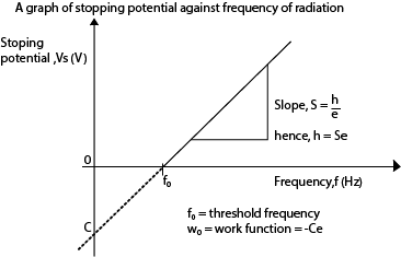

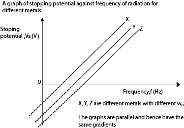
Stopping potential is the minimum potential between the cathode and the anode that prevents the most energetic electrons from reaching the anode
Experiment to measure stopping potential of a metal

- An evacuated electric cell X that has inside it a photo-emissive metal cathode, C of large surface area and an anode A for collecting the electron produced
- A is made negative in potential relative to C.
- The photoelectrons emitted from C when illuminated with a suitable beam experience a retarding potential.
- The p.d V is increased negatively until the current become zero and the stopping potential Vs is noted from the voltmeter.
Example 6
Sodium has a work function of 2.3eV. Calculate the
(i) Threshold frequency
From w0 = hf0
2.3 x 1.6 x 10-19 = 6.63 x 10⁻³⁴f0
f0 = 5.55 x 10¹⁴Hz
(ii) Stopping potential when it is illuminated by light of wavelength 5 x 10⁻⁷m (1eV = 1.6 x 10⁻¹⁹J)

Explanation of the laws of photoelectric emission using quantum theory
The quantum theory states that “light is emitted and absorbed in discrete packets of energy called photons”
When light is incident on a metal surface, each photon interacts with a single electrons giving it all its energy. The photon is absorbed if its energy is greater than the work function and if it is less, the photon is rejected.
Increasing the intensity of light increases the number of photons striking the metal surface per second. Therefore more electrons are emitted per second and the photocurrent increases with intensity.
Increasing the frequency of incident radiation increases the energy of each photon and therefore the maximum kinetic energy of the liberated electrons increases with the frequency of radiation.
Increasing the intensity of light only increases the number of photons but not the energy in each photon. Hence kinetic energy of the emitted electrons is independent of the intensity of the incident radiation
Failures of the wave theory (classical theory) to account for the photoelectric emission
1. Existence of threshold frequency
According to the classical theory, the energy of the incident radiation depends on its intensity; the greater the intensity of illumination, the greater the supply of energy. This would imply that radiations of high enough intensity should cause emission even when the frequency is below the minimum value. However as long as the incident radiation is below the threshold frequency, no photoelectrons are emitted however intense the incident radiation is
2. Instantaneous emission of photoelectrons
Classical theory suggests that the energy of the incident radiation would be continuously absorbed by the electron. Implying that the electron would take some time to accumulate sufficient energy that would enable them escape from the metal surface. By this theory, emission of photoelectrons would not be instant
3.Variation of K.E of the emitted photoelectrons
According to the classical theory, increasing the intensity of the incident radiation would mean more incident energy and a greater maximum K.E of the emitted photoelectrons. But instead the maximum K.E of the photoelectrons emitted depend on the frequency of the incident radiation.
4.Variation of photoelectric current with intensity
When the intensity of illumination is increased, the number of photons incident on the metal surface also increases. Hence more free electrons in the metal receive sufficient energy to escape. The rate of emission increases and therefore a large current flows. Thus the size of the photocurrent depends on the intensity of the incident radiation. However, According to classical theory, increase in the intensity would increase the K.E of the emitted electron and they would escape with greater speed instead, which is false
The Photocell
• Photocells change radiation into electric current.
• In their construction, the anode is made thin so that it does not obstruct the incident radiation
• It’s placed in vacuum because the metals are reactive

• When radiations fall on the cathode, electrons are emitted and these electrons are collected by the anode.
• If the anode is positive respect to the cathode, current flows in the circuit
Types of Photocells
(a) Photo emissive cells
(b) Photovoltaic cells
(c) Photoconductive cells.
Photo emissive Cell

When radiation of frequency f greater than f0 (threshold frequency) of the photo emissive cathode is incident on the cathode, electrons are emitted, they move to the anode and current flows in the external circuit.
The size of the current increases with the intensity of the incident radiation.
If the light beam is interrupted, the current stops flowing.
When the device is connected to a suitable relay circuit, it can be used to open doors, act as a burglar alarm or as switching device.
Photovoltaic Cell
It generates an e.m.f dependent on the intensity of the incident radiation. Such cells are used in solar panels, solar calculators and for powering electronic watches.
Photoconductive Cell
It consists of a plate of a material called photoconductor, whose resistance decreases when it is illuminated by light or infrared radiation, mounted in an evacuated glass bulb. An applied voltage causes current to flow which increases with the intensity of the radiation due to release of electrons in the photoconductor.
Experiment to show the variation of current (I) with p.d (V)

A monochromatic light i.e. constant frequency is used.
The photocurrent (I) is measured for increasing values of V at constant light intensity.
For negative values of V, the polarity of the battery is reversed.
The experiment is repeated by increasing the intensity of the radiations; by moving the light source closer to the photocell
A plot of graphs of photocurrent (I) against the p.d V is shown below.
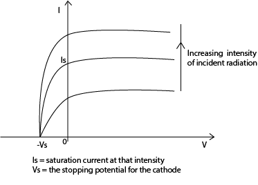
N.B: The photocurrent is not zero even when the p.d is zero. This is because electrons are emitted with varying velocities (K.E), some of which are sufficient to overcome the repulsive electric field and reach the anode.
Example 7
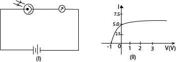
A photocell is connected in the circuit as shown in figure (I) above. The cathode is illuminated with monochromatic light of wavelength 390nm and the current I in the circuit recorded for different p.d V applied between the anode and the cathode. The graph fig (II) shows the results obtained.
(a) Find the maximum K.E of the photoelectrons
From the graph Vs = -1V
K.Emax = eV = 1.0 x 1.6 x 10-19 = 1.6 x 10⁻¹⁹
(b) What is the work function of the cathode in eV?
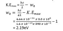
(c) If the experiment is repeated using monochromatic light of wavelength 310nm, where would the new graph cut the V-axis?

Hence the graph would cut the v-axis at – 1.83V
Applications of Photocells
- Photoelectric Emission)
- A photocell can make doors open automatically in buildings when a light beam is interrupted by somebody/obstacle.
- Intruder alarm systems. The intruder intercepts the infrared beam falling on a photocell, hence cutting off of current. This interruption therefore sets the alarm on.
- Photovoltaic cells are used in solar panels, calculators and for powering electronic watches.
- Used as automatic devices for switching on light at night when it tries to darken or when the frequency of the light reduces.
- Automatic counting machines in industries.
- Production of sound from a film
Differences between x-ray production and photoelectric effect:
Differences between x-ray production and photoelectric effect:
| Photoelectric effect | X-rays |
| Electromagnetic radiation falls on metal surface and electrons are emitted | Fast moving electrons hit the metal target and x-rays (electromagnetic radiation) is produced |
| Little heat is generated | A lot of heat is generated |
Example 8
A 100mW beam of light of wave length 4.0 x 10⁻⁷m falls on a caesium surface of a photocell.
(i) How many photons strike the caesium surface per second?

(ii) If 80% of the photons emit photoelectrons. Find the resulting photocurrent.
Number of electrons emitted = 2 x 10¹⁷s-1 x 80%
= 1.6 x 10¹⁷
Current = ne
= 1.6 x 1017 x 1.6 x 10-19
= 2.56 x 10⁻²A
(iii) Calculate the kinetic energy of each photoelectron if the work function of caesium is 2.15eV.

Experimental evidence for quantum theory
(i) Photoelectric effect:
To liberate an electron from a metal surface, a quantum or packet of energy called the work function which is characteristic of the metal surface has to be supplied
![]()
(ii) Optical spectra:
A line in the optical emission spectrum indicates the presence of a particular frequency f of light and is considered to arise from loss of energy which occurs in an excited atom when an electron jumps directly or in steps from a higher energy level E2 to lower energy level E1.
The frequency of the packet of energy emitted is given by hf = E2 – E1. .
(iii) X-ray line spectra:
Electron transition from one shell to another leads to liberation of energy in packets characteristic of the target atom.
Differences between classical theory and quantum theory
Differences between classical theory and quantum theory
| Classical(wave) theory | Quantum theory |
| It allows continuous absorption and accumulation of energy. | No continuous absorption allowed. The energy is either absorbed or rejected. |
| Energy of radiation is evenly distributed over the wave front. | Energy is radiated, propagated and absorbed in packets (quanta or photons). |
| What matters is total energy of the incident radiation (beam). | What matters is the energy of individual photon. |
Electron dynamics
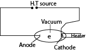
Consider an electron moving from cathode to Anode.
- Let the p.d between the cathode and anode be V. The electron will be accelerated by the electric field and hence it gains K.E.
- If the electron starts from the cathode with zero velocity and reaches the anode with velocity ums-I, then the K.E gained by

Deflection of an electron in a magnetic field
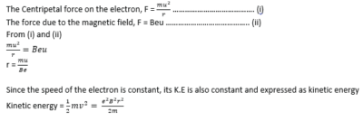
Consider an electron entering a uniform magnetic field of flux B, at right angles to its direction of motion with velocity u.

When the electron enters the field, the magnitude of its speed u does not change because the magnetic force is perpendicular to the direction of the electron, But instead its direction changes and the electron moves in a circular arc.
Let r be the radius of the circular arc (path)
Example 9
An electron moves in a circular path at 3.0 x 10⁶m/s in a uniform magnetic field of flux 2.0 x 10⁻⁴T. Find the radius of the path.
[mass of an electron me = 9.11 x 10⁻³¹kg, e = 1.6 x 10⁻¹⁹C]

Crossed fields
Crossed fields are fields in which a uniform magnetic field and a uniform electric field are perpendicular to each other producing deflections opposite to each other. If the magnetic force and electric force in the crossed fields are of the same magnitude, there is no deflection on charged particles that enter such fields.

The slits S1 and S2 confine the particles into a narrow beam as they enter the crossed fields. The only particles that emerge at slit S3 are those which are undeflected, and therefore they emerge with the same velocity u.
The electric force FE due to the electric field = eE
The magnetic force Fm due to the magnetic field = Beu
For crossed fields FE = Fm
eE = Beu

Therefore, crossed fields can be used as a velocity selector of particles of a single velocity from a beam of particles of different velocities.
Example 10
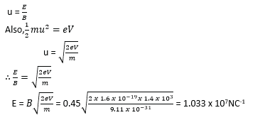
An electron accelerated by a p.d of 1.5KV passes through an electric field crossed with a uniform magnetic field of flux density 0.45T. Calculate the value of the electric field needed for the electron to emerge undeflected.
Solution
Determination of Specific Charge (e/m) of an electron: (J.J Thomson’s Method)

- The electrons are produced thermionically by a hot filament cathode and are accelerated towards a cylindrical anode and pass through it.
- The small hole on the anode confines the electrons to a narrow beam.
- When both the electric field and the magnetic field are off, the electrons reach the screen at X and cause fluorescence.
- If the velocity of the electrons on emerging from the anode is u then

The magnetic field is switched on and the beam is deflected to position Y.
In order to bring the beam back to the original position X, the electric field is switched on and adjusted until the beam is at X again.
This implies that The magnetic force = the electric force

Example 11
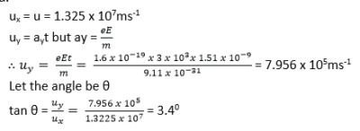
A beam of electrons is accelerated through a p.d of 500V and enters a uniform electric field of strength 3.0×10³V/m created by two parallel plates of length 2.0cm. Calculate:
(a). the speed of the electrons as they enter the field.

(b). the time that each electron spends in the field.

(c). the angle from which the electrons have been deflected by the time they emerge from the field.
Motion of an electron in an electric field
Consider two parallel plates AB and PQ such that AB is vertically above PQ and at a distance d apart. Let l be the length of the plates and V the p.d between the plates.
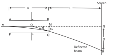
This electric force is directed towards the positive plate causing the deflection of the beam as shown above.

Since the electric field intensity is vertical, there is no horizontal force acting on the electron. Hence the horizontal component of the velocity of the electron does not change.
Let u be the horizontal component of the velocity of the electron entering the electric field.
Motion in the X-direction

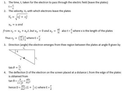
Thus the motion of an electron in electric field is parabolic
Note
Example 12
A beam of electrons is accelerated through a p.cd of 2000V and is directed mid-way between two horizontal parallel plates of length 5.0cm and separation of 2.0cm. The p.d across the plates is 80V.
(a). Calculate the speed of the electrons as they enter the region of between the plates.

(b). Find the speed of the electrons as they emerge from the region between the plates.

(c). Explain the motion of the electrons between the plates.
It is parabolic
Example 13
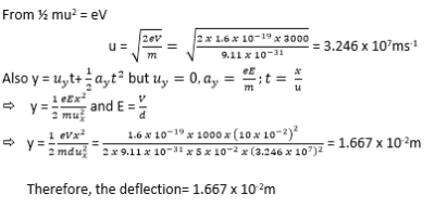
An electron gun operated at 3×10³V is used to project electrons into the space between two oppositely charged parallel plates of length 10cm and separation 5cm. Calculate the deflection of the electrons as they emerge from the region between the charged plates when the p.d is 1.0×10³V.
Millikan’s Oil drop experiment
This is used to determine electronic charge e

Procedure
– Set up of the apparatus is as shown above
– Oil drops are introduced between the plates P1 and P2 by spraying using the atomizer.
– These oil drops are charged in the process of spraying by friction but the charge may be increased further ionization due to X-rays.
– The oil drops are strongly illuminated by an intense light from the arc lamp so that they appear as bright spots when observed through a low power microscope.
– With no electric field between the plates, record the time t1 taken for drop to fall from P1 to P2.
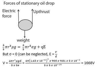
– The electric field between the plates is turned on and adjusted so that the drop becomes stationary.
Case 1
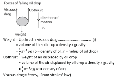
With no electric field, the oil drop falls with a uniform velocity v1 called terminal velocity
Case 2
When the electric field is applied so that the drop is stationary, the drop has no velocity and no acceleration.

Precautions
To improve on the accuracy of the experiment, the following precautions need to be taken into account
1) A non-volatile oil or low vapor pressure oil should be used to reduce evaporation. Evaporation would alter the mass of the drop or radius of the drop
2) The experiment is enclosed in a constant temperature enclosure. This is to eliminate convection currents and changes in the viscosity of air as a result of temperature changes.
3) An X-ray tube is used to increase the charge of the oil drop.
Example 14
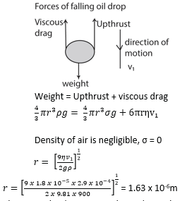
Oil droplets are introduced into the space between two flat horizontal plates, set 5.0mm apart. The plate voltage is then adjusted to exactly 780V so that one of the droplets is held stationary. Then the plate voltage is switched off and the selected droplet is observed to fall a measured distance of 1.5mm in 11.2s. Given that the density of the oil used is 900kgm-3 and the viscosity of air is 1.8 X 10⁻⁵Nsm-2, find;
(i) The radius of the oil drop

(ii) The charge of the droplets
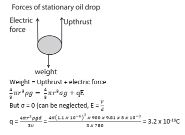
(iii)The number of electrons on the drop

Example 15
a) Calculate the radius of a drop of oil of density 900kgm-3 which falls with a terminal velocity of 9 x 10⁻⁴m/s through air of viscosity 1.8 X 10⁻⁵Nsm-2.
b) If the charge on the drop is -3e, what p.d must be applied between the plates 5.0mm apart in order to keep the drop stationary?
Thermionic emission and thermionic diode
Gaseous discharge in a discharge tube
A ‘discharge’ is the passage of electricity through a gas at low pressure less than about 50 mm Hg.
A discharge tube is a hard glass tube connected to a vacuum pump; the tube contains two electrodes which are connected to an external high voltage source. The discharge tube contains air (which is a poor conductor of electricity) at very low pressure since it is evacuated.

Action of a discharge tube
– As the air pressure inside the tube decreases, the gas starts to ionize while the p.d inside the tube is constant.
– When one gas atom is ionized, the electron escaping from it also ionizes other gas atoms.
– Streams of positive ions and electrons are created which move to the cathode and anode respectively.
– Current is thus generated
Changes that occurs in a discharge tube as pressure is reduced to very low values.

Cathode Rays
These are streams of fast moving electrons that travel from the cathode to the anode.
Properties of cathode rays
– They travel in straight lines.
– They are negatively charged.
– They are deflected by both electric and magnetic fields.
– They cause fluorescence in some metals e.g. Zinc metal.
– They ionize gaseous atoms.
– They affect photographic plates.
– They produce X – rays when stopped by a metal target.
– They possess momentum therefore they have mass.

The following are the main features of CRO
- a hot filament emits electrons
- The grid G has a negative potential with respect to the filament and controls the number of electrons entering and reaching anode A1
- Anodes A1 and A2 accelerate the electron beam at a high speed the screen
- Deflecting system consist of Y- and X-plates; Y-plated deflect the beam vertically while X- plates deflect the beam horizontally.
- The screen is coated with zinc sulphide to display the arrival of the beam by emitting light when struck by the beam
- Carbon coating prevents the electron beam from the influence of any external electric field.
Mode of action of a C.R.O
– The cathode is heated using a low voltage supply and produces electrons by the process of thermionic emission.
– The electrons are accelerated and focused into a fine beam by the anode to fall on the screen producing a bright spot.
– The brightness of the spot on the screen is controlled by the control grid
How the grid controls the brightness of the spot of a C.R.O
– The grid is connected to a negative potential.
– If the potential of the grid is more negative, only few electrons with high K.E (or speed) will pass through it. Thus the screen will be less bright.
– If the potential of the grid is less negative, many electrons will pass through it. Thus the screen will be brighter.
Deflection; Time-base.

If a battery were connected between the Y-plates, so as to make the upper one positive, the electrons in the beam would be attracted towards that plate, and the beam would be deflected upwards. In the same way, the beam can be deflected horizontally by a potential difference applied between the X-plates.
When the oscillograph is in use, the alternating potential difference to be examined is applied between the Y-plates. If that were all, then the spot would be simply drawn out into a vertical line.
To trace the wave-form of the alternating potential difference, the X-plates are used to provide a time-axis.
A special valve circuit generates a potential difference which rises steadily to a certain value, as shown in (i), and then falls rapidly to zero; it can be made to go through these changes tens, hundreds, or thousands of times per second.
This potential difference is applied between the x-plates, so that the spot is swept steadily to the right, and then flies swiftly back and starts out again.
This horizontal motion provides what is called the time-base of the oscillograph.
On it is superimposed the vertical motion produced by the Y-plates; thus, as shown in Fig. ii) above, the wave-form of the potential difference to be examined is displayed on the screen.
Uses of a C.R.O
1) Measures both a.c and d.c voltages
2) Measures frequencies or compare frequencies
3) Measures phase difference
4) Measure small time intervals (used as a clock)
5) Displays wave forms
6) diagnosis heartbeat and brain in hospitals.
Comparison of CRO with a moving coil Voltmeter.
a) The C.R.O has very high impedance. It gives accurate voltages than a moving coil voltmeter.
b) A CRO can measure both d.c and a.c voltage. A moving coil voltmeter measures only D.C voltages unless a rectifier is used.
c) A CRO has negligible inertia as compared to a moving coil voltmeter. The C.R.O respond almost instantaneously.
d) CRO doesn’t give direct voltage readings.
Uses of Oscillograph
In addition to displaying waveforms, the oscillograph can be used for measurement of voltage, frequency and phase.
- A.C. voltage
An unknown a.c. voltage, whose peak value is required, is connected to the Y-plates. With the time-base switched off, the vertical line on the screen is centered and its length then measured as shown in figure (i) below. This is proportional to twice the amplitude or peak voltage, V0. By measuring the length corresponding to a known a.c. voltage V, then V0 can be found by proportion.
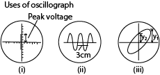
Alternatively, using the same gain, the waveforms of the unknown and known voltages, V and V0, can be displayed on the screen. The ratio V/V0 is then obtained from measurement of the respective peak-to-peak heights.
2. Comparison of frequency
If a calibrated time-base is available, frequency measurements can be made. In Fig. (ii) above, for example, the trace shown is that of an alternating waveform with the time-base switched to the ‘5 millisec/cm’ scale. This means that the time taken for the spot to move 1 cm horizontally across the screen is 5 milliseconds. The horizontal distance on the screen for one cycle is 3 cm. This corresponds to a time of 5 x 3 ms or 15·0 ms = 15 x 10-3 seconds, which is the period T.
![]()
If a comparison of frequencies, f1, f2 is required, then the corresponding horizontal distances on the screen are measured. Suppose these are d1, d2 respectively.

3. Measurement of phase
Positive rays
– Positive rays are streams of positively charged particles.
Production of positive rays in a discharge tube

- Positive rays are produced when a stream of electrons is passed through a vapor (gas) in discharge tube.
- The electrons dislodge electrons from the atoms producing positively charged ions.
- The positive ions are accelerated towards perforated cathode.
- The ions pass through the slits and are further accelerated.
- These ions constitute a stream of positive rays.
Properties of positive rays
1) They travel in straight lines
2) They are positively charged
3) They are more massive compared to cathode rays
4) They are reflected by strong magnetic fields
5) They have smaller specific charge (q/m) compared to the cathode rays (this is because they are more massive than the cathode rays)
6) They are deflected by strong electric fields in opposite direction to that of the cathode rays in the same field
The Bainbridge Mass Spectrometer
Consists of three main parts, namely
– Accelerating electric field
– Velocity selector
– Deflecting chamber
Uses of a Bainbridge mass spectrometer
1. To measure the specific charge of positive rays or ions
2. To separate isotopes of an element
3. To determine the atomic masses of the positive rays or ions
Determination of specific charge using a Bainbridge spectrograph

T1 and T2 are tracers on photographic plate, S1, S2 and S3 are slits
Mode of Action
- Positive ions are produced in a discharge tube and admitted as a beam through slits S1 and S2.
- The beam then passes between insulated plates P, Q, connected to a battery, which create an electric field of intensity E.
- A uniform magnetic field B1, perpendicular to E is applied over the region of the plates and all ions, charge e with the same velocity, v given by B1ev =Ee will then pass undeflected through the plates and through a slit S3.
- The selected ions are deflected in a circular path of radius r by a uniform perpendicular magnetic field B2 and an image is produced on a photographic plate as shown.
In this case
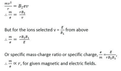
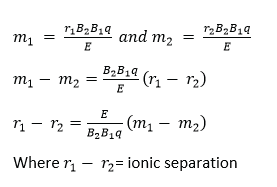
Since the ions strike the photographic plate at a distance 2r from the middle of the slit S3, it follows that the separation of ions carrying the same charge is directly proportional to their mass. Thus a ‘linear’ mass scale is achieved.
Ionic separation is obtained by
Example 16
The magnetic flux density in both fields is 0.4T and the electric field in the velocity selector is 2×10⁴Vm.
(i)nWhat is the velocity of an ion which goes un deviated through the slit system
B1 = B2 = B = 0.4T and E = 2 x 10⁴Vm
For crossed fields in the velocity selector
B1qu = Eq
![]()
(ii) The source is set to produce singly charged ions of magnesium isotopes as Mg – 24 and Mg – 26. Find the distance between the images formed by the isotopes on the photographic plate, assuming the atomic masses of the isotopes are equal to their mass numbers numerically.
In the deflection chamber, Fm = Fe

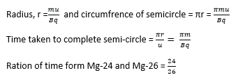
(iii) Calculate the ratio of the times the two isotopes take to complete a semi-circle. {Assume 1U = 1.67×10⁻²⁷kg and e = 1.60×10⁻¹⁹C}
The atom
The atom
The atom consists of a nucleus containing protons and neutrons (Nucleons) surrounded by orbits carrying electrons. The number of protons in an atom is referred to as atomic number whereas the sum of protons and neutrons in the nucleus of an atom is the mass number of the atom (nucleon number)
Atoms of the same element with the same number of protons but different number of neutrons are called isotopes.
Atoms with the same number of nucleon are called isobars.
Rutherford model of an atom
According to Rutherford, an atom consists of a positively charged core (nucleus) which contains most of the mass of the atom and it’s being surrounded by orbiting electrons occupying the biggest part of the atom. To confirm this, Rutherford investigated the scattering of alpha particles by a thin foil of heavy metal e.g. gold.
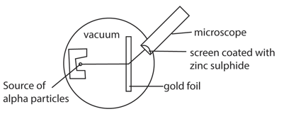
In this experiment, α (alpha particles) from a source are incident onto a thin metal foil and a glass screen coated with zinc sulphide is used to detect the scattered alpha particles which form scintillations (flash of light) as they hit the screen.
It is carried out in a darkened room so that the scintillations can be seen clearly and the apparatus is evacuated to ensure that the particles are able to reach the screen without losing energy.
By rotating the screen about the metal foil and then counting the number of scintillations produced at various positions in equal interval of time, it is observed that majority of α-particles go through undeviated, few of the α-particles are scattered through small angles and very few are deviated by more than 900.

The large angle scattering is due to a single encounter between an alpha particle and the intense positive charge (nucleus). Since very few of the particles are scattered through large angles, this confirms that the nucleus occupies a small portion of available space in an atom. This disapproves the plum-pudding model which was initially popular.
Rutherford’s model however had some opposition on theoretical ground that the orbit electrons are accelerating thus emitting electromagnetic radiations at the expense of their own energy and consequently they would slow down and spiral into the nucleus.
To resolve this, Bohr assumed that each electron moves in a circular orbit centered on the nucleus and necessary centripetal force is being provided the electrostatic force due to the nucleus and this is concretized by the following Bohr’s proposals.
The Bohr Model of the Atom Bohr’s postulates
(i) Electrons in atoms exist only in certain discrete orbits and while in these orbits they don’t radiate energy.
(ii) Whenever an electron makes a transition (jumps) from one orbit to another of lower energy, a quantum of electromagnetic radiation is given off. The energy of the quantum of radiation emitted is given by: hf = Ei – Ef
Where;
Ei is the energy of the electron from the initial orbit,
Ef is the energy of the electron in the final orbit,
f is the frequency of the radiation emitted and h is Planck’s constant.
![]()
Failure

Note: The Bohr atom consists of a massive positively charged nucleus occupying a small space at the center being surrounded by orbiting electron which don’t emit electromagnetic radiation as they revolve.
Applications of Bohr’s postulates to the hydrogen atom
Consider the electron in a hydrogen atom to be in a circular orbit of radius r about the nucleus.
An electron has kinetic energy to its motion round the nucleus and potential energy in electrosatic field of the nucleus.
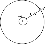
Kinetic energy of electron in the orbit

Potential energy of an electron in orbit
The potential due to the charge e on the nucleus at a distance r is given by

The radii of the Bohr orbits
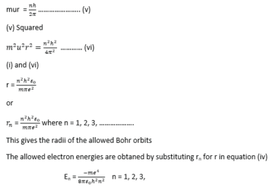
Angular momentum of the electron in an orbit of radius r is given by (mu) x r
i.e. the product of linear momentum and radius
Applying Bohr’s postulates regarding angular momentum
Bohr’s assumptions
Bohr’s assumptions
- Each electron moves in a circular orbit with the nucleus as its center.
- The necessary centripetal force is provided by the electrostatic force of attraction between the positively charged nucleus and the negatively charged electron.
Bohr’s failures
- It can only explain spectra for simpler atoms with few electrons such as hydrogen
- It cannot explain fine structure of spectral lines of hydrogen
- His model assumes that the electron orbits are circular yet they are elliptical.
Note:
- The energy of the electron is always negative. This means that the work has to be done to remove the electron from infinity where it is considered to have zero energy. The electron is thus bound to the atom.
- When rn is increased, n also increases and the energy En becomes less negative.
- The lowest energy level or energy state occurs when n = 1 and is referred to as the ground state. The other energy levels (energy state) are called excited energy states.
- A transition of an electron from energy level n1 to n2 will lead to a radiation of energy hf such that E1 – E2 = hf

Distance of closest approach
Consider an alpha particle with charge, 2e incident directly towards the nucleus of charge +ze.
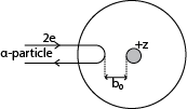
An alpha particle approaching directly the nucleus is slowed down and comes to rest a distance, b0 from the nucleus and then repelled back.
The kinetic energy possessed by an approaching alpha particle is given by ½ mv2
The electrostatic potential energy of alpha particle and the nucleus at closest distance of approach is given by

Example 17
A beam of α-particle of 4.2MeV is incident to a nucleus of a gold atom. Calculate the distance of closest approach (Z = 79)
![]()
Energy Level
- According to Bohr’s model of an atom, electrons are arranged in permitted (allowed) orbits of definite amount of energy. These orbits are also known as energy levels of an atom
- The energies of the electrons in an atom have only certain values called energy levels of the atom.
- All atoms of a given element have the same set of energy levels and these are characteristic of the element i.e. they are different from those of other elements.
- Energy levels are calculated using Bohr model and expressed in eV
- The lowest energy level of an atom is known as ground state.
- Electrons have least energy in the ground state.
- The atom becomes ionized when an electron receives energy to just exceed its highest energy level and leave the atom.
- The highest energy level given the value zero and lower energy levels are negative.
Energy level in the hydrogen atom
The spectrum of atomic hydrogen contains distinct groups of lines. The three major ones include; Lyman series, the Balmer series and the Paschen series

The spectral lines of hydrogen are experimental evidence for the existence of discrete or separate energy levels of the hydrogen atom.
Transition involving LYMAN SERIES involve high energy changes. Those in PASCHEN SERIES involve lowest energy changes.
Lyman series involve the transition to the energy state n1 and the resulting radiation emitted is the Ultra-Violet.
Balmer series involve the transition to the energy state n2 and the resulting radiation emitted is the visible spectrum.
Paschen series involve the transition to the energy state n3 and the resulting radiation emitted is the Infra-red.
-The energy required to remove the electron in the ground state to infinity is the ionization energy .
![]()
Transitions
- A transition of an electron at a higher energy level Ex to a lower energy level Ey results in loss of energy given by: (Ex – Ey) = hf; Where h is Planck’s constant, f is the frequency of the electromagnetic radiation.
- Sometimes an electron may pass through an intermediate state Em to the final energy state. It emits frequencies f1 and f2 given by Ex – Em = hf1 and Em – Ey = hf2
- When an electron absorbs energy, it jumps from a lower energy level to a higher energy level. The atom is then said to be excited. Such an atom is unstable and to gain stability, the electron falls back to its original energy level while releasing the energy in a form of radiations (light).
Note:
1) Excitation Energy: This is the energy required to raise an atom from its ground state to an excited state.
2) Ionization Potential: This is the potential required to enable the electron to escape completely from the atom.
3) Ionization Energy: this the energy required by an electron to escape completely from the atom
Example 18
Some of the energy levels of mercury are shown in the diagram below. Level 1 is the ground state level occupied by the electrons in an unexcited atom
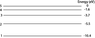
Calculate the ionization energy of mercury atom in Joules
![]()
= 0 – (-10.4)
= 10.4eV
= 10.4 x 1.6 x 10-19
= 1.66 x 10⁻¹⁸J
(ii) Calculate the wavelength of the radiation emitted when an electron moves from level 4 to level 2.

X-Rays
X- Rays are electromagnetic radiations of short wavelength produced when fast moving electrons are stopped by heavy metal target.
Production of X – Rays

Mode of operation
- The filament is heated by a low voltage supply and the electrons are emitted by thermionic emission.
- The concave focusing cathode focuses the electrons from the filament onto the target.
- These electrons are accelerated towards the anode by the high voltage between the filament and the Anode.
- When the electrons (cathode rays) strike the metal target, about only 1% their kinetic energy is converted to X-rays and the 99% of their kinetic energy is converted to heat, which is conducted away by the cooling fins.
Note.
- The target is made of a high melting point metal.
- ii) The X-ray tube is covered by a lead shield with a small window for the X-rays to prevent the leakage of the X-rays.
Intensity of X-rays (Quantity or number of X-rays)
- The intensity of X- rays in an X – ray tube is proportional to the number of electrons colliding with the target.
- The number of electrons produced at the cathode depends on the filament current supply.
- The greater the heating current, the greater the number of electrons produced and hence more x- rays are produced.
- Therefore the intensity of X- rays is controlled by the filament current.
Penetration of X – rays (quality)
- Penetration power of X-rays depends on the kinetic energy of the electrons striking the target.
- The higher the accelerating voltage, the faster the electrons produced.
- Faster electrons possess higher kinetic energy and shorter wavelength x-rays of greater penetration power are produced.
- Hence penetrating power of X-rays is determined by the accelerating Voltage across the tube.
Types of X-rays
There are two types of X-rays, namely: Hard X-rays and soft X- rays
Hard X-rays:
- They are produced when a high p.d is applied across the tube.
- They have very short wave lengths
- They have a high penetrating power. This is because they have very short wavelengths
Soft X-rays:
- They are produced by electrons moving at relatively lower velocities than those produced by hard X –rays.
- They have longer wavelengths.
- They have a low penetration power compared to hard x-rays. This is because of their long wavelengths
Note:
- Hard X-rays can penetrate flesh but are absorbed by bones, they are therefore used to study bone fractures.
- Soft X-rays are used to show malignant growths since they only penetrate soft flesh. They are absorbed by such growths.
Properties of X –rays
- They travel in a straight line at a speed of light in vacuum
- They are not deflected by both magnetic and electric fields. This indicates that they carry no charge.
- They penetrate all matter to some extent. Penetration is least in materials with high density and atomic number e.g. lead.
- They ionize gases through which they pass.
- They affect photographic plates.
- They cause fluorescence in some materials.
- They cause photoelectric emission
- They are diffracted by crystals leading to an interference pattern.
Uses of X-rays
- Structural analysis, stresses, fractures in solids, castings and welded joints can be analyzed by examining X-ray photograph.
- Crystallography; Orientation and identification of minerals by analysis of diffraction patterns using Bragg’s law.
- Medical uses;
- Analytical uses. These include location of fractures, cancer and tumour/defective tissue absorbs x-rays differently from normal tissue.
- Therapeutics use for destroying cancerous cells and tumours. 4. Detection of fire arms at international airports
Health hazards caused by x-rays:
- Destroy living cells in our bodies especially hard X-rays.
- Cause Gene mutation (genetic changes in our bodies).
- Cause damage of our eye sight and blood. Produce deep skin burns.
NOTE: It’s highly important to remember that each time you are exposed to X-rays, your health is also at risk yet we cannot live without them
Safety precautions:
- Avoid unnecessary exposure to X-rays.
- When exposure is necessary, keep it as short as possible.
- X-ray beams should ONLY be restricted to the body part being investigated.
- A worker should wear a shielding jacket with a layer of Lead.
- Exposure should be avoided for unborn babies and very young children.
Example 19
In an X-ray tube, the current through the tube is0.1mA and accelerating p.d 1.5kV. Calculate the:
(i) The number of electrons striking the anode per second
I = ne where n is the number of electrons striking the anode per second
![]()
(ii) The speed of electron striking the anode

(iii) The rate at which cooling fluid at 100 must be circulated through the tube if the anode is to be maintained at 350
[Assume all electrical energy is converted into heat energy and S.H.C of fluid is 2000Jkg-1K-1]

Example 20
In an X-ray tube, 90% of the electrical power supplied is dissipated as heat. If the accelerating potential difference across the tube is 75kV and 742.5W is dissipated as heat, calculate the:
(i) Current in the tube

(ii) Number of electrons arriving at the target per second
I = ne where n is the number of electrons per second
![]()
Example 21
The current in a water-cooled X-ray tube operating at 60kV is 30mA. 99% of the energy supplied to the tube is converted into heat which is removed by water at a rate of 0.06kgs-1. Calculate the:
(i) Number of electron hitting the target per second
![]()
(ii) Rate at which energy is being supplied to the tube
Power = IV = 30 x 10-3 x 60 x 103 = 1800W
(iii) Rate of change in temperature of cooling water

X-ray diffraction
The wave nature of X-rays can be confirmed by their diffraction with crystals
Laue’s experiment:

- After long exposure of the crystal to the x-rays, the photographic plate is developed and printed.
- A regular pattern of dark sports called Laue spots is observed around a central dark image.
- The pattern is due to the X-rays which have been scattered by interaction of the X-rays with the electrons in the atoms of the crystal.
- The regularity of the Laue spots implies that the atoms in a crystal are arranged in a regular pattern.
Bragg’s law
When A parallel beam of monochromatic X-rays incident on a crystal is reflected from successive atomic planes, the reflected rays super-impose, forming an interference pattern.

For constructive interference to occur, the path difference is equal to the whole number of wavelength
Thus BC + CD = nλ
dsinθ + dsinθ = nλ
2dsinθ = nλ where n = 1, 2, 3, 4 …
Example 22
A second order diffraction mage is obtained by reflection of X-rays at atomic planes of a crystal in sodium chloride at glancing angle of 110. Calculate the atomic spacing of the planes if the wavelength of X-rays is 4 x 10-11m.
From 2dsinθ = nλ
![]()
Example 23
X-ray of wavelength 1.55 x 10⁻¹⁰m are incident on a copper crystal of atomic spacing 4.25 x 10⁻¹⁰m
(i) Calculate the smallest angle at which radiation will be first reflected.
From 2dsinθ = nλ
![]()
(ii) If the temperature of the crystal is increased by 6000, calculate the change in the angle that will be obtained. [the coefficient of linear expansion of copper is 1.7 x 10⁻⁵K-1]

Example 24
A monochromatic beam of X-rays of wavelength 2 x 10⁻¹⁰m is incident on a set of cubic planes in potassium chloride crystal. First order diffraction is observed at glancing angle 18.50.
Calculate
(i) The inter-atomic spacing on potassium chloride.
From 2dsinθ = nλ
![]()
(ii) The density of potassium chloride if the RFM is 75.5grams
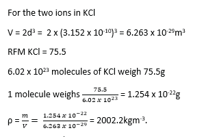
X-rays Emission spectrum
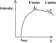
The spectrum consists of two major components, i.e. the continuous (background) spectrum and the very sharp line spectrum superimposed onto the background spectrum.
The continuous spectrum is produced when electrons make multiple collisions with the target atoms in which they are decelerated. At each deceleration, X-rays of differing wavelength are produced.
The shortest Wavelength X-rays are produced when electrons lose all their energy as X-ray photon in a single encounter with the target atoms. The wavelength of the X-rays at this point is known as the cut off wavelength. At cut off wavelength, energy in an X-ray photon equals kinetic energy of the electron;
![]()
The line spectrum
At high tube voltages, the bombarding electrons penetrate deep into the target atoms and knock out electrons from inner shell. The knocked out electrons occupy vacant spaces in higher unfilled shells putting the atom in excited state and making them unstable.
Transition of an electron from higher to lower energy levels results in an emission of X-ray photon of energy equal to energy difference between the energy levels.
If the transition ends in the K-shell, it produces K-series and if the transition ends in L-shell. It produces L-series.
Radioactivity
This is the spontaneous disintegration of unstable atoms with emission of particles like alpha, beta particles and gamma radiations.
The nuclei of some elements like uranium, thorium are unstable undergo radioactive decay in order to gain stability.
The three types of radiations can be identified by:
1) Their different penetrating powers/abilities
2) Their ionizing powers
3) Their behavior in electric and magnetic fields.

- They are the least penetrating with a range of a few centimeters in air and can be stopped by paper.
- They produce intense ionization in any gases through which they pass.
- They are deflected by both electric and magnetic fields.
- Their direction and size of deflection suggests that:
(i) They are positively charged
(ii) They are relatively heavier particles.Modern physics for a-level notes
- Alpha particles are therefore a Helium nuclei containing 2 protons and 2 neutron
Beta – particles
- They are more penetrating than the alpha particles with a range of several centimeters in air and a few millimeters in aluminum.
- They are less ionizing than the alpha particles.
- They are more easily deflected than the alpha – particles, and their size and direction of deflection suggest that:
(i) They are negatively charged
(ii) They have a very small mass
Gamma rays
- They are highly penetrating
- They ionize gases to a very small extent
- They are not deflected by both the magnetic and electric fields, indicating that they are uncharged.
.
Rules governing radioactivity
(i) When a radioactive substance decays by emission of alpha particle, its atomic number A reduces by 2 and it mass number Z reduces by 4
![]()
(ii) When a radioactive substance decays by emission of beta particle, its atomic number A increases by 1 and it mass number Z remains constant
![]()
When a radioactive substance decays by emission of gamma rays, both its atomic number A and it mass number Z remains constant
![]()
The decay law
It states that the rate of disintegration of the nuclei in a given time is propotional to the number of atoms present
![]()
where N- number of atoms present, t = time, λ is a constant and negative because the number of atoms are reducing
The decay law can also be expressed as
N = N0e–λt
where No is the initial number of disintegrating atoms.
The decay constant is the fractional number of atoms that are disintegrating per second
Half-life ((t½) is the time taken for the number of atoms in a radioactive element to reduce to half the original value.

Activity is the rate of disintegration of a radioactive substance =λN
Example 25
A sample of radioactive material initially contains 1018 atoms. If the half-life of the material is 2 days, calculate the
(i) number of atoms remaining after 5days

(ii) percentage that decayed after 5days

(iii) activity of the sample after 5days
Activity, A = λN = 0.3465 x 1.7684 x 1017 = 6.127506 cx 1016
Radioactive detector
Geiger Muller Tube (GMT)
The GMT is used to detect the presence of X- rays, Gamma rays, beta particles and if the window of the tube used is very thin, it detects even alpha particles.
Structure

The thin mica window allows the passage and detection of the weak penetrating alpha particles. The GM tube is first evacuated then filled with Neon, Argon plus Halogen gas which is used as a quenching agent.
Mode of operation
- When an ionizing particle enters the tube through the window, argon atoms are ionized.
- The electrons move to the anode while the positive ions drift to the cathode.
- A discharge occurs and the current flows in the external circuit.
- A p.d is obtained across a large resistance, R which is amplified and passed to the scale.
- The magnitude of the pulse registered gives the extent to which ionization occurred.
Note:
- The anode wire must be very thin so that the charge on it produces an intense electric field close to its surface.
- This electric field is used to accelerate the electrons towards it from the cathode.
Characteristics of a GMT
The graph below is obtained when the counter rate is plotted against the operating voltage.

OA – the operating voltage is not enough to attract the ions to the respective electrodes and hence the counter registers no reading. This voltage (i.e. at A) is called the threshold voltage.
AB – the applied p.d not enough to attract all electrons; hence increasing the p.d increases the number of electrons being attracted and hence increase in counter rate.
BC – here the count rate is constant. This is called the plateau region.
– Between BC, all the negative ions are able to reach the anode because the operating voltage is large enough to attract them.
– Full avalanche is obtained along the entire length of the anode.
– Here the tube is said to be operating normally.
CD: – The count rate increases rapidly because the quenching process becomes ineffective and eventually a continuous discharge occurs which might damage the tube.
Definitions.
Dead time. This is the time taken by the positive ions to move from the anode to the cathode. During this time the tube is insensitive to the arrival of further ionizing particles.
Recovery time. This is the second period of insensitivity. During this period, pulses are produced but not large enough to be detected. In this time, argon ions are being neutralized by the quenching gas before they reach the anode.
Threshold voltage is the voltage below which there is no sufficient gas amplification to produce pulse high enough to be detected
Experiment to determine a half-life of radioactive substance using GM- tube
- Switch on the GM-tube, note and record the background count rate, A.
- Place a source of ionizing radiation near the GM-window.
- Note and record the count rate recorded the count rate at equal intervals.
- For each count rate recorded subtract the background count rate to get the true rate.
- Plot a graph of the count rate against time.

Find time t1 taken for the activity to reduce to A/2 and t2 taken for activity to reduce to A/4 from A/2
![]()
The diffusion cloud chamber

Mode of action
- The base of the chamber is maintained at low temperature, about -800c by the solid carbon dioxide while the top of the chamber is at room temperature, and so there is a temperature gradient between the top and the bottom of the chamber.
- The air at the top of the chamber is saturated with alcohol vapor from the felt ring. This vapor continuously diffuse downwards into the cooler regions so that the air at the chamber is super saturated with alcohol vapor.
- Radiations from the radioactive source S cause the ionization of the vapor.
- The ionizations from the radioactive source S cause condensation of the vapor on the ions formed, hence the path of the ionizing radiations are traced by series of small droplets of condensation.
- The thickness and length of the path indicate the extent to which ionization has taken place.
- Alpha particles produce short, thick, continuous straight tracks
- Beta particles which are less massive produce longer, thin but straggly paths owing to collisions with gas molecules
- Gamma radiations are uncharged and for ionization to take place, it must collide with an atom and eject an electron which then ionizes the vapor.
The Wilson cloud chamber

Mode of action
When the piston is quickly moved, the air in the chamber is saturated with alcohol vapour undergoes an adiabatic expansion and it cools.
The dust particles are carried away leaving behind air which is dust free. This is the subjected to controlled expansion making it super saturated.
It is then simultaneously subjected to ionizing radiation from a source, S. the vapour condenses on the ions formed to form water droplets around the ions
These are then illuminated and photographed by the camera.
The nature of the path formed reveals the type of ionizing agent.
Ionizing Chamber

A radiation source on the brass flat form causes ionization of air in the chamber producing electrons and positive ions.
The electrons move to the metal can and positive ions drift to the central metal rod.
Movement of the ions to the electrodes causes discharge and current pulse flows in external circuit.
The current sensitive detector detects current.
The magnitude of current detected shows the extent to which ionization takes place.
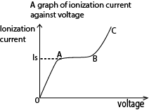
Region OA:
Current detected increases gradually but p.d is not large enough to prevent recombination of the ions.
Region AB. (saturation region)
Current is almost constant, all ions reach the electrode before recombination but there is no secondary ionization.
Region BC (gas amplification)
Current increases rapidly for small increase (change) in p.d because secondary ionization takes place due to primary ions being produced. This implies many ion pairs, thus a larger current detected.
Artificial radiations
These can be produced by
Bombarding a nucleus of stable element with neutrons in a nuclear reactor
Bombarding a nucleus of stable element with a charged particle such as alpha or beta particles.
Uses of Radioistopes and radioactivity
In industry
- Sterilization of food
- Detecting leakages in pipes
- Determining thickness of paper
- Determining the rate of wear
In medicine
- Treatment of cance
- Tracer of disease
- Sterilizing medical equipment
Health hazards
- May cause cancers
- Eye damage
- Cause sterility
- Cause mutation
Unified Atomic Mass unit U
Definition: the Unified Atomic Mass Unit (U) is one – twelfth the mass of one atom of carbon – 12.
Derivation
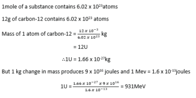
Binding energy (B)
The mass of the nucleus of atom is always less than the total mass of its constituent nucleons (protons and neutrons).
The mass of the nucleus of atom is always less than the total mass of its constituent nucleons (protons and neutrons). The difference in mass is called the mass defect.
Mass defect = (mass of nucleons) – mass of the nucleons mass of the nucleus
The reduction in mass is because when the nucleons are combining to form the nucleus, some of the mass is released as energy in the form of gamma rays.
In order to break the nucleus and separate the nucleons, the same amount of energy which was released has to be supplied to the nucleus. This is called the Binding energy.
Definition:
Binding Energy is the minimum energy required to break the nucleus into its constituent particles and completely separate them from each other.
Binding energy = (mass defect in kg) X (speed of light)2
The higher the binding energy the more stable the nucleus.
Binding energy per nucleon is the ratio of energy required to break a nucleus into free neutrons and protons to the mass number.
![]()
Example 26
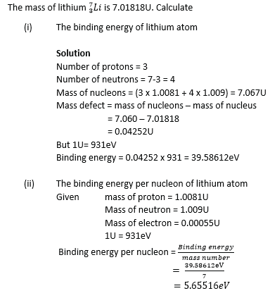
Example 27
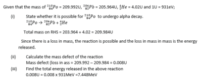
Example 28
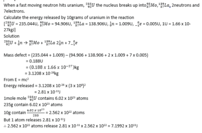
Example 29
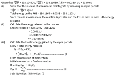
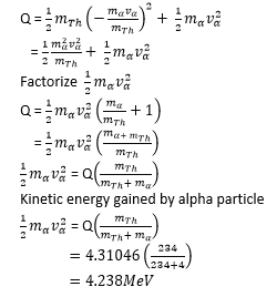
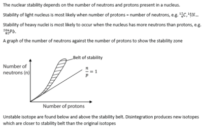
Nuclear stability
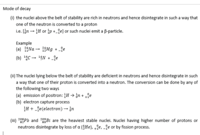
Nuclear fission
This is the splitting of a heavy nucleus into two or more light nuclei accompanied by the release of energy.
Sufficient excitation energy for the nucleus to split may be provided by particle bombardment of the nucleus with protons, neutrons or electrons. E.g.
![]()
Neutrons are preferred as bombarding particles because they do not carry charge and therefore can penetrate deeper into the nucleus.
Uses of nuclear fission
To provide electricity
To manufacture atomic bombs.
Nuclear fusion
It is the union of two lighter nuclei to produce heavier nucleus of higher binding energy per nucleon accompanied by release of energy, e.g.
![]()
Nuclear fusion takes place at high temperature because the nuclei need a lot of kinetic energy to overcome their electrostatic repulsion.
A sketch of Variation of Binding energy per nucleon with mass number relating nuclear fusion and nuclear fission

Note that:
- Two Small nuclei with atomic mass less than 56 each fuse to give a heavier nuclei with smaller mass by higher binding energy to increase stability of nucleon
- A nucleus with atomic mass higher than 56 split to form lighter nuclei of higher binding energy per nuclei
Please download pdf: Modern physics for a-level notes
Compiled by Dr. Bbosa Science
Sponsored by: The Science Foundation College + 256 753 802709

thank you teacher
Thanks you so much I appreciate Dr
Thanks so much
Thanks nice work
Thank you so much.
I would like to be part of the protect.
digitalteachers.co.ug is voluntary project, if you wish please contribute anything educational it willbe uploaded. our mail is digitalteachersuganda@gmail.com
Thanks surely
Thank you so much i do appreciate
Great
Your blog is a source of inspiration for me. Home Improvement
Your writing style is very engaging. Barcelona News
Just great ideas to transform the poor wee