")
Waves in physics (A-level)

WAVES
Definition
A wave is any disturbance from an equilibrium condition that travels with time from one region to another in form of oscillation.
Or
A wave is a means of transfer of energy by a vibrating medium.
Class of Waves
Waves can also be classified as mechanical waves and electromagnetic waves.
Mechanical waves
These are wave which require a material medium for transmission. Mechanical waves include: Sound waves, water waves, waves on strings etc.
Electromagnetic waves
These are wave which do not require a material medium for transmission. Electromagnetic waves include: light waves, radio waves, X-ray, ultraviolet etc.
Differences between mechanical and electromagnetic waves
| Mechanical Waves | Electromagnetic waves |
| Need a medium for transmission. | Do not need a medium for transmission. |
| Cannot travel through vacuum. | Can travel through a vacuum. |
| Relatively slow | Very fast |
Types of waves
There are two kinds of waves namely:
(i) Longitudinal waves.
(ii) Transverse waves.
Longitudinal waves
A longitudinal wave is one in which the direction of the wave motion in the same direction as the vibration.
OR
A longitudinal wave is one in which particles vibrate in direction parallel to wave motion.
Examples of longitudinal waves are sound waves, waves produced by pipes and string instruments. A longitudinal wave has two regions namely: compression and rare faction regions.
Diagram showing motion of particles for longitudinal wave.

C is compression region, R is rare faction region.
Compression region
Compression region is a region in the longitudinal wave where the vibrating particles are very close together. A particle at the centre of compression region moves from the rest position in same direction as the wave.
Rare-faction region
Rare-faction region is a region in the longitudinal wave where the vibrating particles are further apart. A particle at the centre of rare-faction moves from rest position in the opposite direction to that of the wave.
Differences between compression and rare faction regions of longitudinal wave.
| Compression | Rare-faction |
| Vibrating particles are very close together. | Vibrating particles are further apart. |
| A particle at the centre moves from rest position in a direction the same as that of the wave motion. | A particle al the centre moves from rest position in opposite direction to that of the wave motion. |
Transverse waves
Transverse wave is one in which particles vibrate perpendicular to the direction of wave motion.
Example: Water waves, light waves, all electromagnet waves.
A transverse wave has two main regions namely: Crest and Trough.

Crest is a region of maximum upward displacement of particles in a transverse wave.
Trough is a region of maximum downward displacement of particles in a transverse wave.
Differences between a transverse wave and longitudinal wave
| Transverse | Longitudinal wave |
| Particles vibrate perpendicular to the direction of the wave motion | Particles vibrate in a direction parallel to wave motion |
| Has 2 regions crest and trough | It has 2 regions, compression region and rare faction |
| No variation in particle density occurs along the profile | Particle density varies along the wave profile |
| The distance between successive crests or troughs is the wavelength | Distance between successive rarefactions or compression is the wave length. |
| Can undergo polarization | Cannot be polarized. |
General presentation of a wave
A wave can be represented graphically by a sine wave. The curve is drawn by plotting displacement of particles, y against distance of the particle from the source of the wave, x.
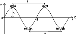
Definition of terms
OC is the equilibrium/resting/mean position.
Displacement is a distance of any particle at any point of the wave from equilibrium position.
Amplitude (A) is a maximum displacement of a particle from its rest position on a wave.
Crest is the point on the wave profile with maximum positive displacement.
Trough is the point on the wave profile with maximum negative displacement.
Cycle or oscillation: This is a complete to and fro motion of a wave. It is equivalent to moving from O to B along the wave profile.
Wavelength, λ. This is the distance between two successive particles in a wave profile which are in phase. Particles are said to be in phase if they are at the same stage of their motion; i.e. have the same displacement from the equilibrium position and are travelling in the same direction.
As applied to a transverse waves, wavelength is the distance between two successive troughs or crests.
Applied to longitudinal waves, wavelength is the distance between two successive compressions or between two successive rarefactions.
The SI unit of wavelength is meters.
Period, T. This is the time taken by a wave to perform one complete cycle or oscillation. It can also be defined as the time taken by a wave to cover a distance of 1 wavelength.
S.I. unit of period is Hertz (Hz) or per second.
Ray is a line perpendicular to wave front which shows the direction of travel of a wave.
Phase is a fraction of a cycle which has elapsed after a particle passing a fixed point
Wave front, any line of section taken through an advancing wave in which all particles are in phase or it is an imaginary line which joins the set of particles that are in phase.
Particles are in phase if they are in the same point in path at the same time and are moving in the same direction.

Velocity of a wave
The velocity of a wave is the speed with which the wave propagates. It can also be defined as the rate of wave travel in meters per second (m/s)
Relationship between v, f and λ
Consider a source of wave that produces waves of frequency, f and wavelength, λ. whenever the source makes one oscillation, the wave travels forward by one wavelength.
If f oscillations are made per second, the wave travels forward by a distance given by
Distance = fλ
But the distance moved per second = v
∴ v = fλ
Wave motion and oscillation motion
Wave motion is a form of oscillation motion.
Oscillation motion is motion where a body or particle move to and fro in the same path.
If the oscillatory motion repeats itself at regular time intervals, then it is periodic motion.
If the periodic motion can be represented by sine curve, if is said to be harmonic motion.
An oscillation is defined as a complete to and fro displacement of a particle from equilibrium position. Oscillation may be mechanical or electrical oscillation.
Mechanical oscillation are those in which energy is passed and stored by vibrating particle.
Electrical oscillation are those in which energy is possessed and stored in electrical and magnetic field.
Types of oscillation
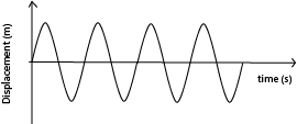
Free oscillation
These are indefinite oscillations that occurs with constant energy and amplitude due to absence of dissipative forces (e.g. friction, air resistance and viscosity).
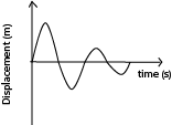
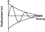
Damped oscillation
These are oscillations that progress with decreasing amplitude and energy due to dissipative forces such that the system loses energy to the surrounding and amplitude of oscillation decreases until the system finally comes to rest. The amplitude of oscillation reduces because the dissipative forces cause the system to progressively lose energy.
There are three types of damped oscillations
Under damped oscillation
These are oscillations in which the system experiences low resistance/dissipative forces such that it loses energy gradually and amplitude of oscillations decrease gradually until the system finally comes to rest.
Critically damped
These are oscillation which occur when a system is displaced but does not oscillate and return to equilibrium position in the minimum possible time. The magnitude of resistive forces is such that they do not allow the system to vibrate past this equilibrium position.
Critical damping is applied in
Moving coil instruments such as ammeters, voltmeters to bring the pointer to rest instantly so that a reading can be taken.
Shock absorbers
Office doors
Over damped oscillations
These are oscillations which occur when a system is displaced and does not oscillate but returns slowly to the equilibrium position
Differences between free and damped oscillations
| Free oscillation | Damped oscillations |
| Amplitude of oscillation remain constant | Amplitude of oscillation decrease with time |
| Wave energy remain constant | Wave energy decrease with time |
| Oscillations occur in absence of dissipative force | Oscillations occur in presence of dissipative forces |
| System oscillates indefinitely | System finally comes to rest |
Forced oscillations
These are oscillations in which the system subjected to some degree of damping is made continuously oscillate by subjecting it to external periodic force
The external periodic force restores the energy lost from the system as a result of dissipative forces.
The frequency of external periodic force is known as forcing frequency.
Progressive waves
A progressive wave is one that consists of disturbance moving from source outwards to the surrounding regions of which energy is transferred from one region to another.
In progressive wave, the wave profile moves from a source to the surrounding region at the same speed as the wave motion. The vibrations of the particles are of the same amplitude and frequency, but the phase of vibration changes from one point to another along the wave.
Phase angle
The phase angle is angular displacement between two wave oscillations. It can also be angular displacement between particles at different points in another profile. Phase angle is represented by φ and it is measured in radians.
Phase difference
The phase difference is the difference in the phase angles at any two points along the wave motion. It is also measured in radians
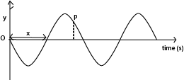
Consider the wave motion below
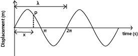
The particle at P is said to lag behind the particle at O by phase difference ∆φ or Xφ determined by the horizontal distance, x of the particle P from particle O and the wavelength of the wave motion.
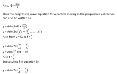
The phase difference is given by the expression; φ = 2πx/λ
Where x = the difference between the two points on the wave motion
λ = the wavelength
φ = the phase difference.
The progressive wave equation
The progressive wave equation is the same as the equation for sine curve,
i.e. y = Asinωt
where y = displacement
A = amplitude
ω = angular velocity
A particle P lags behind the particle O by a phase difference, φ. The displacement of such a particle is given by equation y = Asin(ωt – φ).
This is the equation for a progressive wave moving in the positive x-direction.
For progressive wave moving in opposite direction, the equation is
y = Asin(ωt + φ).
But from circular motion, ω = 2πf
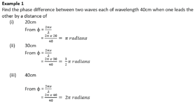
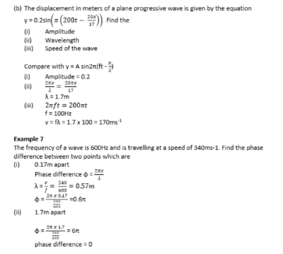
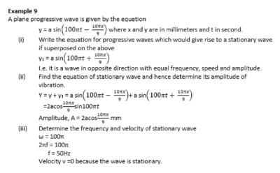
Example 6
Describe how the amplitude of a forced oscillation builds up to constant value.
In forced oscillation, an oscillating system is subjected to an external periodic force which supplies energy to system. This energy builds the amplitude to the required level and then restores the energy lost by friction, viscosity and/or air resistance.
Principle of superposition
When two waves travel through a medium, their combined effect at any point can be found by the Principle of Superposition
This states that the resultant displacement at any point is the sum of the separate displacements due to the two waves.
The superposition principle is used to explain the formation of stationary waves
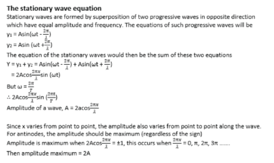
Stationary/standing waves
A stationary wave is a waves in which the wave profile does not move along the medium and the amplitude varies from place to place along the wave.
Formation of stationary wave.
Stationary wave is formed when two progressive waves having the same speed and frequency and approximately equal amplitude but travelling in opposite direction are superposed.
Conditions for formation of stationary waves
Superposition of two waves travelling in opposite direction
The waves should have the same frequency and speed
The waves should have nearly equal amplitude
Progressive waves which agree with above conditions can be obtained when a wave travels along a given path and strikes an obstacle such that it reflected perpendicularly and returns along the same path. The incident and reflected waves superpose to form a stationary wave in which the wave profile does not move along the medium.
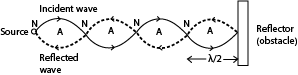
The superposition of the two waves results into points where the particles are permanently at rest. These points are known as nodes. These points midway between successive nodes will have their particles vibrating with maximum amplitude. The points are known as antinodes.
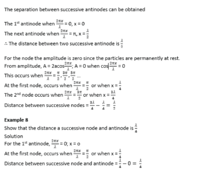
The distance between any two successive nodes or any two successive antinodes is equal to half the wavelength of the stationary waves.
i.e. distance between successive node = λ/2
the distance between successive antinodes =λ/2
the distance between a node and neighboring antinode = λ/4.
A stationary wave unlike progressive waves does not transfer energy since the wave profile does not move along the medium.
Also, at points between successive nodes, all vibrations are in phase.
Characteristics of a stationary wave
- The amplitude of the wave varies from place to place along the wave profile.
- Wave energy is not transmitted along the wave profile.
- It has nodes and antinodes
- At points between successive nodes, the vibrations are in phase
- At nodes, particles are permanently at rest while at the antinodes the particles have maximum displacement.
- The medium is split up into segments. The particles in the segments are out of phase with particles in the neighboring segments by 1800
- In a given segment, the particles attain maximum velocity and acceleration at the same instant.
- Compression and rarefactions do not travel forward as progressive waves. They appear and disappear alternatively in the same place.
- During each vibration, all particles pass simultaneously through their mean position twice with maximum velocity which is different for different particles.
Differences between stationary and progressive waves
| Stationary waves | Progressive waves |
| Each point along the wave has different amplitude of vibration from the neighboring points | The vibration of particles are of the same amplitude. |
| At points between successive nodes the vibrations are in phase i.e. the phase of vibration does not vary. | The phase of vibration of points near each other are all different. |
| They do not transfer energy | They transfer energy from one point to another. |
| The wave profile does not move along the medium | The wave profile moves along the medium with the wave speed. |
| The medium does not move | The medium moves |
NB. The velocity of stationary wave is zero
Wave front
A wave front is a section through an advancing wave along which all particles are in phase.
Along a wave front every particle transmitting the wave is at the same distance from the source of the wave and is in the same state of disturbance.
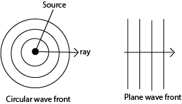
Therefore the two major forms of wave front which are circular and plane fronts.
Circular wave fronts
Consist of wave front that are concentric circles with the source wave at the center. Such wave front can be obtained when a surface of still water is disturbed by a round object.
Plane wave front are wave fronts in which the wave are parallel to each other. Such wave fronts can be obtained when the surface of water is disturbed by plane object such as a ruler.
Light is thought to be propagated to the earth as plane wave fronts.
General properties of waves.
All waves can undergo
Reflection
Refraction
Diffraction
interference
Reflection of waves
This is the bouncing back of waves from an obstacle
Reflection can be shown by standing a straight metal strip as a plane reflector and curved metal strip as concave and convex reflector in water
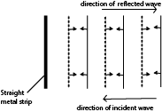
Reflection of waves at plane surface
A straight metal strip attached to a vibrator using vibrations generated by electric motor, is placed in water and another straight metal strip is placed in water parallel to the vibrator. Then the electric motor is switched on and the straight waves are incident normally reflected along the same path as plane waves.
b) Place a straight metal strip at an angle to reflect the approaching wave.
For reflection at plane surface both the incident and reflected waves are straight and have equal spacing because the incident and reflected waves have the same speed and wavelength as the wave is travelling in water of same depth.

Laws of reflection of waves
The incident wave, reflected wave and the normal at the point of incidence all lie in the same plane.
The angle of incidence of waves is equal to the angle of reflection of the wave.
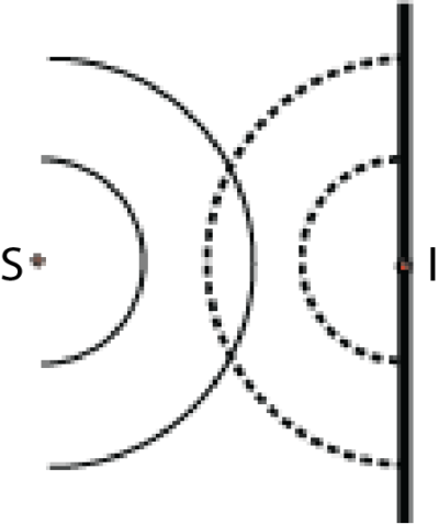
Circular waves Incident on straight reflector the source “S” corresponds to the object and I corresponds to virtual source of the reflected waves,
Reflection of straight waves
Convex reflector

Concave reflector
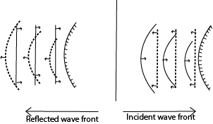
The reflected wave-fronts are circular, converging towards and passing through the principal focus F.
Points to consider when drawing
(a) The focal point F becomes the centre of the circular waves.
(b) The circular waves should be equally spaced. The distance of spacing should be the wavelength.
(c) The spacing for the circular waves should be the same as that for the straight waves.
REFRACTION OF WAVES
Waves formed in ripple tanks can be refracted by placing a sheet of glass in water to make it shallow. The continuous straight waves in the shallow water are found to be closer to one another than in deep water. This implies that the wavelength of the wave is less in shallow water than in deep water. In short the wavelength of a wave in shallow water is shorter even though the frequency is the same.
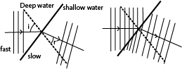
The direction of the wave when it strikes shallow water at a right angle does not change.
The wave speed is reduced in shallow water hence wavelength decreases. So when drawing the refracted waves are closely spaced
The frequency of the wave motion does not change.
Since speed “V” = fλ. In shallow water the wavelength decreases yet the frequency remains constant, so the speed of the wave decreases in shallow water. The wave travels faster in deep water because the wave length increase yet the frequency remains constant.
Refraction results in a wave slowing down the speed and changing direction as the wave enters shallow water.
A glass plate placed in ripple tank at normal to the wave

Refraction of straight waves at curved surfaces
a) Converging refractor

b) Diverging refractor

Interference
Interference is when two identical waves moving in the same direction are superposed on one another. Waves are superposed when one wave is placed on top of the other. For this to occur the amplitudes and frequencies of the two waves should be the same.
Coherent sources are sources which produce waves of the same frequency and amplitude which are always in phase or have a constant phase difference.
In the ripple tank, the two waves are produced by two ball ended dippers attached to the vibrator receiving vibration from the electric motor.

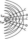
Where:
“C” is constructive interference
“D” is Destructive interference
“S1” and S2 are sources of vibration
From principle of superposition;-
Where the two waves are superposed in the same phase e.g. crests of one wave fall on the crests of another constructive interference occurs.
Where the two waves are superposed such that they are exactly out of phase e.g. crests of one wave are superposed on the troughs of the other identical wave, no disturbance is obtained. These positions are called destructive interference.

Conditions for interference to occur
Superimpose two waves in the same direction
The waves must have the same frequency
The waves must have the same amplitude
The waves must have a constant phase difference.
Path difference as applied in interference
The path difference is the difference in optical paths travelled by the two waves before they meet or superpose.
Consider two sources of waves S1 and S2 producing waves that travel along the Paths AB and CB

Path difference = S1B – S2B
The path difference can be used to predict whether constructive or destructive interference will occur at the point of superposition.
If the path difference is a whole number multiple of the wavelength of a wave, the constructive interference occurs. I.e. for constructive interference to occur the path difference should be zero or a whole number multiple of full wavelength.
Or path difference = nλ where λ = wavelength of a wave, n = 0, 1, 2, 3 …
If the path difference is an odd multiple of half wavelength, the destructive interference occur. i.e. for the destructive interference to occur,
Path difference = (λ(2n + 1))/2; n = 0, 1, 2, 3 ….
Differences between constructive and destructive interference
| Constructive interference | Destructive interference |
| Occurs when the crest of one meets the crest of another or when the trough of one wave meets a trough of another. | Occurs when a crest one wave meets a trough of another |
| Reinforcement occurs | Cancellation occurs |
| Resultant intensity is maximum or higher | Resultant intensity is minimum or lower |
| Occurs when the path difference is a whole number multiple of full wavelength i.e. path difference = 0 or nλ | Occurs when the path difference is an odd number multiple of a half wavelength
(λ(2n +1))/2 |
Example 10
Two speakers producing sound of the same frequency are place 50m apart facing each other, an observer walks from one speaker to the other along the line of the speakers.
(i) What does the observer hear?
The observer hears alternate loud and soft or near silence. The loudness and near to silence sound come at equal interval.
(ii) Explain the observation in (i) above.
The loud speakers act as coherent sources producing sound of the same frequency. The two waves from the loud speakers superpose and interference occurs.
Constructive interference occur where the path difference is a whole number of the wavelength of sound so that reinforcement occurs and loud sound is heard.
Destructive interference occurs where the path difference is an odd multiple of half wavelength of sound and no sound is heard.
DIFFRACTION OF WAVES
Diffraction is the spreading of waves when they pass through apertures or around obstacles.
The general phenomenon of diffraction may be illustrated by using water waves in a ripple tank.
For diffraction to occur the dimension/size of aperture or obstacle must be of the order of the wavelength of the wave; i.e. the width of the aperture must be of the same order as the diffracted wave.
The diffraction of Plane waves through a narrow and wide aperture is illustrated below

Generally, the smaller the width of the aperture in relation to the wavelength, the greater is the spreading or diffraction of the waves
Secondary, the longer the wavelength of the wave to be diffracted the greater the diffraction or spreading.
Light waves have very short wavelengths that diffraction around obstacles of normal size is negligible that we unable to see around corners while sound waves of longer wavelength are reasonably diffracted that we are able to hear around corner.
In summary diffraction of the wave depends on
Dimension of the aperture
Wavelength of the wave.
Huygens’ Principle.
Every point on a wave front may be regarded as a source of secondary spherical wavelets which spread out with the wave velocity. The new wave front is the new envelope of these secondary wavelets.
Diffraction at a single slit
Diffraction at a single slit is explained by Huygens’ Principle.
Suppose parallel light is incident on a narrow rectangular slit A and B
Each point on the same wave front between A, B acts as a secondary centre of disturbance, and sends out wavelets beyond the slit.
All the secondary centres are coherent, and their combined effect at any point such as P or Q can be found by summing the individual waves there, from the Principle of Superposition.
At P, most of the wavelets arrive in phase causing constrictive interference leading to formation of the central bright band.
On outwards from P, an increasing number of wavelets arrive out of phase and hence the bright bands reduces in intensity until a dark band is formed where all wavelets arrive out of phase.
Farther away from P parallel to AB, the intensity rises again to a much smaller maximum producing less bright band than at P.
More and more alternative bright and dark bands of reducing intensities are formed further from P parallel to AB where wave wavelets meet in phase and out of phase respectively.
The graph of intensity against distance and corresponding diffraction band are shown below.

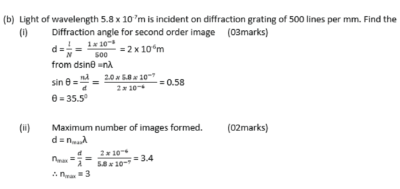
Diffraction of light at more than one slit using diffraction grating
A diffraction grating is a large number of close parallel equidistant slits, ruled on glass or metal using diamond pencil
Like single narrow rectangular slit, when parallel monochromatic light is incident normally to two or more slits of a diffraction grating each slit produces an image with a bright central or principal maximum diffraction band, together with subsidiary maxima diffraction bands which are much less bright. This time, however, the pattern is crossed by a number of interference bands, which are due to interference of waves from different slits.
Deriving an expression for angular position of nth order principal maximum produced by transmission diffraction grating.
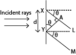
Suppose X and Y are corresponding points in consecutive slits where XY = d, and the grating is illuminated normally by monochromatic light of wavelength, λ, the direction, θ, the diffracted ray XL, and YM have path difference, XA
From sin θ = XA/d;
XA = dsin θ
The path difference for all corresponding points in the two slits have the same path difference, dsinθ. So other pairs of slits throughout the grating are treated the same way.
Also for bright or principle maxima to be obtained, the path difference = nλ.
∴ dsin θ = nλ; where d= slit separation, λ = wavelength, θ = angular momentum

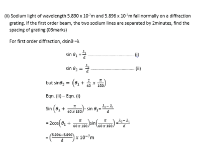
Measurement of the wavelength of monochromatic light using a diffraction grating and a spectrometer.
(a) Make the following adjustment
- The collimator C is adjusted such that parallel rays emerge from it.
- The telescope is adjusted so that parallel rays entering it are brought to a focus at the cross wire near its eyepiece.
- The table is levelled so that the plane of P is parallel to the axis of rotation of the telescope.
(b)

- The grating is placed on the table so that its plane is normal to incident light
- The readings of the first diffraction image are observed on both sides of the normal at T1 and T2.
- The angular difference is 2θ, and the wavelength is calculated from λ = d sin θ, where d is the spacing of the slits, obtained from the number of lines per centimeter of the grating.
- If a second order image is obtained for a diffraction angle θ, then λ = d sin θ⁄2.
Difference s between the spectra produced by a prism and that produced by diffraction grating
| Prism | Diffraction grating |
| – Produce single spectrum at a time
– Shorter wavelengths are deviated most – Produce less pure spectrum |
– Many spectra at a time
– Longer wavelength are deviated most. – Produce more pure spectrum |
Example 12
A diffraction grating of spacing d, is illuminated normally with light of wavelength, λ.
(i) Derive the condition for concurrence of diffraction maxima. (03marks)

(ii) Describe briefly the intensity distribution on screen placed beyond the grating (02marks)
The central principle maxima is the most intense; the intensity decreases on the either side.
(iii) What is the effect on diffraction pattern when grating with larger number of lines is used (02marks)
The diffraction maxima (image) becomes narrower and shaper
Refractive index of a medium using Huygens’ Principle at Plane Surface
Consider a beam of parallel rays between LO and MD incident on the plane surface of the medium from air in the direction shown, and suppose that a plane wave front has reached the position OA at a certain instant,
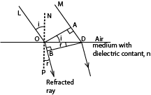
In figure above, each point between O, D becomes a new centre of disturbance as the wave front advances to the surface of the medium, and the wave front changes in direction when the disturbance enters the medium.
Suppose that t is the time taken by the light to travel from A to D. The disturbance from O travels a distance OB, or vt, in the medium in a time t, where v is the velocity of light in medium.
At the end of the time t, the wave fronts in the medium from the other secondary centres between O, D reach the surfaces of spheres to each of which DB• is a tangent.
Thus DB is the new wave front in the water, and the ray OB which is normal to the wave front is consequently the refracted ray.
Since c is the velocity of light in air, AD = ct.
Now


Interference of light waves
The conditions necessary for permanent interference fringes between two sources of light
- The wave trains must have nearly the same or equal amplitudes.
- There must be a constant phase relationship between the two wave trains.
- The source must be very close to each other.
- The screen must be very as far as possible from the sources compared to separation of light sources.
NB: Since emission of light is always spontaneous; the above conditions are only possible if the source of waves is the same.
Division of wave front
This is a process of getting two coherent waves from a single wave front.
This may be achieved by using Young’s double slits or biprism or diffraction grating
Formation light interference pattern by division of wave front using double slits.
One of the first demonstrations of the interference of light waves by division of wave front was carried out YOUNG in 1801

A source, S, of monochromatic light in front of a narrow slit C, and two very narrow slits A, B, close to each other, in front of C.
S is narrow, the light which emerges from A and B is coherent since it comes from the same wave front
Interference thus takes place in the shaded region, where the light beams overlap forming bright and dark bands on either side of O on a screen T, where O is on the perpendicular bisector of AB where light from A overlaps that from B.
As AO= OB, a bright band is obtained at O.
At a point P close to O, such that BP – AP = λ/2, where λ is the wavelength of the light from S, a dark band is obtained.
At a point Q such that BQ – AQ = λ, a bright band is obtained; and so on .for either side of O.
The band are due to interference since covering A or B, the bands disappear.
Constructive interference (maximum intensity) occurs when the two waves meet at a point when they are in phase. This occurs when the path difference between the waves is an integral multiple of wavelength.
Destructive interference (minimum intensity) occurs when the two waves meet when they are completely out of phase. This occurs when the path difference between waves is an odd multiple of half the wavelength
Note that
- If the source slit S is moved nearer the double slits the separation of the bands is unaffected but their intensity increases.
- If the distance apart d of the slits is diminished, keeping S fixed, the separation of the bands increases.
- If the source slit C is widened, the bands gradually disappear. The slit C is then equivalent to a large number of narrow slits, each producing its own band system at different places. The bright and dark bands of different systems therefore overlap, giving rise to uniform illumination.
It can be shown that, to produce interference bands which are recognizable, the slit width of C must be less than >λD’/d, where D’ is the distance of C from the two slits A, B. - If one of the slits, A or B, is covered up, the bands disappear.
- If white light is used the central band is white, and the bands either side are colored. Blue is the color nearer to the central band and red is farther away.
The path difference to a point O on the perpendicular bisector of the two slits A and B is zero for all colors, and consequently each color produces a bright band here. As they overlap, a white band is formed. Farther away from 0, in a direction parallel to the slits, the shortest visible wavelengths, blue, produce a bright band first.
Production of two coherent sources using a biprism

- A prism of a very large angle is placed with its refractive edge facing a monochromatic source of light, S.
- Light incident on face L is refracted to appear to come from a point S1 and that incident on Q appears to come from S2 due to refraction.
- The two sources are coherent since they originate from the same source S leading to interference where they superpose.
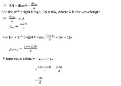
Separation of Bands in Young’s double slit experiment

- A and B are coherent sources.
- Suppose waves from A and B superpose at P to form bright fringe, then BP – AP = mλ
- OP = ym = distance P to O; the center of the band system, where MO is the perpendicular bisector of AB
and length PN = PA is described on PB, - The path difference BN = BP – AP = mλ
- In practice AB is very small compared to PM thus, AN meets PB practically at right angle and thus θ is very small that dsinθ = dtanθ
Example 14
With reference to Young’s double slit experiment,
(i) Explain how interference pattern is formed.
Solution
- When two coherent waves travel in a medium, they meet and superimpose.
- Where they meet in phase, constructive interference takes place and intensity is increased (or maximum)
- Where they meet out of phase, cancellation takes place and intensity reduces (minimum)
- Patterns of alternative regions of maximum and minimum intensities are formed that form interference pattern.
(ii) State what happens to the fringes when the source of light is moved nearer to the slits.
The intensity of fringes increase but their separation remain unaffected.
(iii) State what happens to fringes when the separation of slits is changes
Increase in separation of slits reduces fringe separation.
(iv) Describe the appearance of fringes when white light is used
- When white light is used, colored fringes are observed.
- The central fringe is white, followed by blue and red fringes farther off.
- Outwards the colors overlap leading to white illumination
Measurement of the wavelength of monochromatic light using Young’s double slit method
Monochromatic light from a small lamp is made to illuminate the double slit A and B as shown below.

- The adjacent fringes separation, y, is found by measuring the distance Y between a known number (n) of fringes using a travelling microscope which is moved along the perpex ruler; (note that fringes are equally spaced).
y = Y⁄n
- From y = λD/d where D is the distance of slits from the screen and d = the distance between the slits A and B.
λ = dy/D
Example 15
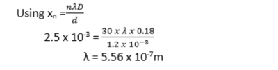
In an experiment to determine wavelength of light using Young’s method, two slits, a separation of 1.2mm were used. When the screen was placed 18.0cm from slits, 30 bright fringes occupying a distance 2.5mm was obtained. Find wavelength of light used (04marks)
Slit separation, d= d= 1.2 x 10⁻³m
Number of bright fringes, n =30
Distance from center of nth fringe, xn = 2.5 x 10⁻³m
Distance from the slits to screen, D = 18.0cm = 0.18m
Appearance of Young’s interference fringes pattern using source of white light
- A central white fringe with colored edges is observed due to overlapping colored fringes. Here the path difference is zero
- Since the violet color has the lowest wavelength, then a violet fringe will be the first fringe on the either side of the central white fringe. The farthest fringe is red
- After a few fringes, the fringe pattern become invisible due to much overlapping
Interference in thin air wedge films
Thin air wedge is formed by inclining two thin glass slides at a small angle θ.

- When monochromatic light is incident normally inclined glass slides at O;
- Part of light is reflected on the bottom part of the top glass slide while part of the transmitted light is reflected at B on the top part of the bottom glass slide.
- The two reflected waves are thus coherent since both have originated from the same centre of disturbance at 0, and they produce an interference phenomenon if brought together by the eye or in an eyepiece.
- Their path difference is 2t, where t is the small thickness of the air-film at 0.
- The wave reflected at bottom part of top glass slide suffers no phase change while that reflected from top part of lower glass slide at B at boundary with a denser medium suffers a phase change of π due to reflection which is equivalent to an additional path of λ/2
- Therefore a dark band is formed at the point of contact A of the slide instead of bright fringe.
- Hence for constructive interference (bright fringes), (2t+ (λ/2))=nλ, for n = 1, 2, 3…
Destructive interference (dark fringes) 2t =nλ, for n = 1, 2, 3 …
NB. If the wedge surf aces make perfect optical contact at one edge, the bands are straight lines parallel to the line of intersection of the surf aces. If the glass surfaces are uneven, and the contact at one edge is not regular, the bands are not perfectly straight.
Thickness of Thin Foil in air wedge
If there is a bright band at C at the edge of the foil, the thickness b of the foil is given by 2b = (m + (1/2))λ, where m is the number of bright bands between A and C.
If there is a dark band at C, then 2b = m λ.
Thus by counting m, the thickness b can be found.

Angle θ of the air wedge
- The small angle θ of the wedge is given by b/L , where L is the distance AC, and by measuring L with a travelling microscope focused on the air-film, θ can be found.
- When the separation of fringe is y, and wavelength length of light is λ
- Then, tanθ = λ/2y
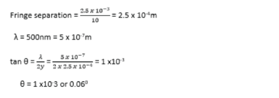
Example 20
Two glass slides are separated by a thin wire to form an air wedge. When the wedge is illuminated normally by light of wavelength 5.6 x 10⁻⁷m, a total of 20 fringes occupying a distance of 15mm are obtained. Calculate the angle of the wedge.

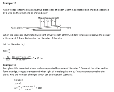
Example 21
An air wedge is formed by placing two glass slides of length 5.0cm in contact at one end and a wire at the other end as shown in the figure below
Viewing from vertically above, 10 dark fringes are observe to occupy a distance of 2.5mm when the slides are illuminated with light of wavelength 500mm. Determine the diameter of the wire. (04marks)
Solution
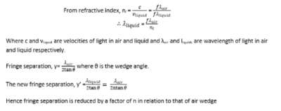
Replacing the air with a liquid in air wedge.
- If a liquid wedge is formed between the plates, the optical path difference becomes 2nt, where the air thickness is t, n being the refractive index of the liquid.
- An optical path difference of λ now occurs for a change in t which is n times less than in the case of the air-wedge.
- The spacing of the bright and dark bands is thus n times closer (reduces) than for air, and measurement of the relative spacing enables n to be found.
Example 22
Explain what will be observed if a liquid is introduced between the slides (02mark)
Experiment how flatness of surface can be determined by interferences from air wedge.
- The surface under test is made to form an air-wedge with a plane glass surface of standard smoothness as shown below.
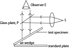
- A parallel beam of monochromatic light from source, S, is reflected from a glass plate, P to fall normally to the air wedge.
- Light reflected by the air wedge is observed.
- Irregularity in the surface of test specimen will show up as irregularity in the fringe pattern.
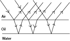
Reasons for appearance colored oil drop on a rainy day.
Then white light incident on the oil film, is partly reflected and partly refracted.
Dispersion occurs due to refraction.
The dispersed rays are reflected at oil-water interface.
The light reflected from both surface meet and superpose in air.
Constructive superposition of colored rays give colored fringes. Hence colored oily surface.
Newton’s ring
It is an example of interference in which a pattern of dark and bright concentric circles are observed when monochromatic light is reflected from a converging lens of large radius of curvature placed on a plane sheet of glass.

- Air cell is formed between the lens and the glass plate
- Some light is reflected from the lower surface of the lens while some of that transmitted is reflected from the top side of the glass plate.
- The light reflected from the top side of glass plate undergo a phase difference of 1800 equivalent to a phase difference of λ⁄2. Thus a dark band is formed at B where the apparent phase difference is 0.
- Then, where the thickness of the air is t; bright ring is formed when 2t = (n + (1/2))λ and a dark ring is formed when 2t = nλ; λ is the wavelength of light, n = 0; 1; 2; 3; …..
Polarization of light
Transverse waves can undergo polarization while longitudinal waves like sound waves do not.
Definition
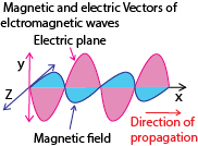
Plane polarized light is one whose electrical vectors varies in only one plane perpendicular to the direction of travel of the wave.
Unpolarized light is whose magnetic and electrical vibrations occur in more than one plane
Polarization is the phenomenon where light is absorbed by a medium in such a way that transverse vibrations in a perpendicular direction is allowed to pass through. The emergent light is thus polarized.
Polarization of light can prove that light is transverse and also electromagnetic wave.
Electromagnetic waves are transmitted by varying electric and magnetic fields and the vibrations therefore occur in electric and magnetic vectors. These vectors are always perpendicular to each other and also perpendicular to the direction of propagation of light.
Identifying plane polarized light.
- A sheet of Polaroid is held in the path of the plane polarized light and rotated slowly about an axis perpendicular to it.
- When all light is absorbed in a particular direction, then it is polarized.
A Polaroid is a material which transmits only those vibrations of light occurring in a certain perpendicular direction.
Method of producing plane polarized light
(a) Selective absorption
Unpolarized light is made incident on a plane sheet Polaroid. The transmitted light will be completely polarized.
(b) Reflection
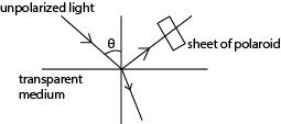
- A narrow beam of light is made incident on transparent medium.
- The reflected light is observed through a Polaroid.
- The angle of incidence is varied
- At each angle of incidence, the polaroid is rotated about the axis along the light incident on it
- At one angle of incidence, the light gats cut off the observer as the Polaroid is rotated.
- The reflected ray is now completely polarized.
- The angle of incidence ip at which all light is polarized is given by ip = tan-1 n; where is the refractive index of the material. (Brewster’s law)
Example 23
A parallel beam of Unpolarized light is incident on a transparent medium of refractive index 1.62. It is reflected as plane polarized light. Calculate the angle of incidence in air and angle of refraction in the medium
Using Brewster’s law; n = tan ip
ip = tan-1 1.62 = 58.30
r = 90 – ip
= 90 – 58.3 = 31.70
(c) Double refraction
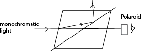
- A narrow beam of monochromatic light is made incident on nicol prism and viewed from the opposite side as shown above
- The angle of incidence is gradually increased or changed and at each angle, the Polaroid is rotated about an axis through its plane.
- At one point, the emergent light is plane polarized.
Note that;
Some crystals such as calcite and Iceland spar exhibit a property known as double refraction where they split unpolarized light into two polarized light rays; ordinary and extraordinary rays.
Uses of polarized light.
(1) Polarized light is used in measurement of the concentration of sugar in a solution
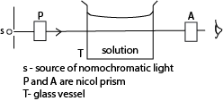
- The apparatus are arranged as above
- First without the solution, the prism A called analyzer is rotated until the emergence light from T is completely extinguished. This orientation is noted.
- T is filled with sugar solution, on looking through A, light can now be seen.
- A is then again rotated until light is extinguished. This point is noted.
- The angle θ between the two positions is noted.
- The angle of rotation θ is proportional to the concentration.
(b) It is used in stress analysis
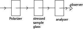
- The apparatus is arranged as above
- The polarizer and analyzer are Polaroid which are crosses with respect to each other so that light does not pass through.
- When a piece of stressed glass is placed between the Polaroids, a pattern of interference fringes can be seen.
- The intensity of light depends on the degree if stress and hence the region and degree of stress is determined
(c) In film to give illusion of three dimension (orography)
(d) In liquid crystal display
Sound waves
Sound is a form of energy produced by vibrating objects. It travels as a longitudinal wave through a material medium.
Production
Sound is produced by vibrating objects. Vibrating objects cause nearby surrounding air molecules to vibrate. When these vibrating air molecules reach our ear, sensation of sound is produced. A sound wave is a longitudinal wave
Propagation of sound
Sound waves need a material medium for transmission so that the vibrating objects cause the nearby molecules of the medium to vibrate
Experiment to show that sound needs a material medium for the transmission

Switch on the electric bell
Switching on the electric bell, a loud sound is heard
Removal of air gradually
On gradually removing the air by a vacuum pump, the loudness of sound gradually dies away.
No sound is heard when all the air has been completely removed though the hammer is seen hitting the gong.
This shows sound waves need material medium like air, liquid or solid for transmission.
The speed of sound waves depends on:-
(i) Temperature.
(ii) Density and elasticity of the medium.
(iii) Wind in the case of air.
How each factor affects the speed of sound waves?
Density: The speed of sound waves is higher in denser medium than in less denser medium. This is the reason why the speed of sound is higher in solids than in liquids and gases because solids are generally more denser.
In a steel rod for example, the speed of sound is about 5000ms-1 yet in water the speed of sound is 1500ms-1 because steel is denser than water.
In daily life, an approaching train can easily be detected by human ears positioned close to the rails than in air. This is explained from the fact that sound waves travel faster through solids than through air as solids are generally denser than air.
Temperature: Increasing the temperature, increases the speed of sound in air greatly because the speed of vibrating air molecules increases with temperature.
However in solids and liquids, increasing the temperature, decreases the speed of sound waves because solids and liquids become less dense as temperature increases.
Wind in the case of air: The speed of sound waves increases if the direction of sound wave travel is the same as that of the wind. If the direction of sound waves travel is opposite that of wind, the speed decreases.
Note: Pressure change in air (gases) does not affect the speed of sound wave because density of air is negligibly affected by change in pressure.
Properties of sound waves
Reflection
Refraction
Diffraction
interference
Reflection
Sound is bounced back from obstacles in similar manner to light. The reflected sound is called an echo.
Laws of reflection of sound waves state:-
i) Incident sound wave, reflected sound wave and the normal at the point of incidence all He in the same plane,
ii) The angle of incidence of sound waves is equal to angle of reflection of sound waves.
Experiment to show reflection of sound waves
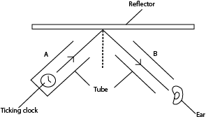
(a) Producing sound waves
Sound waves produced by the clock at the end of tube A are reflected at the hard surface reflector.
b) Moving tube B
The ear is put at the end of the tube B and the tube B is moved until the ticks of the clock are loudest. This is the direction of reflected sound wave.
Note: Hard surfaces reflect sound waves while soft surfaces absorb sound waves.
ECHOES
An echo is reflected sound waves
Echoes are produced by the reflection of sound from a hard surface. Echoes are often heard in the neighborhoods of large houses, high walls, cliffs etc.
I echoes are often heard in the big churches, halls etc. They are not heard in a small room or class-room because the reflected sound waves return very quickly and mix up with the original sound wave.
Echoes are troublesome in lecture halls, cinema etc. To reduce echoes in such places, the walls are covered with soft thick porous materials.
Furniture and people in halls also reduce echoes. So many echoes are produced in empty halls compared to one filled with people because bodies of people are soft so they absorb some of the sound.
Reverberation
If the reflecting surface is nearer, the echo joins the original sound which then seems to become prolonged. This is called reverberation.
Implications of reverberations
- To some degree, reverberation is desirable in concert halls to stop the hall sounding dead so that hearing in such places is improved.
- However, too much reverberation causes confusion.
The time taken by a particular intensity of sound to die away is the reverberation time.
Experiment to measure the speed of sound (echo method)
Two people one claps and the other records the time, while standing at a known distance from a high wall. The time taken for the sound wave to travel to and from the wall is recorded.
The exercise is repeated many times so that the average time is obtained.
Speed of sound = (2 x distance)/ Average time

Refraction of sound waves
Refraction of sound waves occurs when the speed of the wave changes as it moves from one medium to another of different density. The speed of sound waves in air is affected by the air temperature. When sound waves pass through layers of air at different temperature they are refracted i.e. turned into another direction. On a hot day sound waved are bent upwards away from the earth where they otherwise travel faster.

In the evening when the air near the ground becomes cool, refraction of sound is towards the earth, making it easier to hear distant sound as the range of sound is more.
Radios are clearer at night than during day because at night the sound waves are bent down towards the cool earth making the range of sound more.
Interference of sound waves
C – Constructive interference
D – Destructive interference
- Overlapping sound waves produce regions of louder sound by constructive interference and regions of quiet sound by destructive interference.
- If two loud speakers are connected to the same audio frequency generator, they produce sound waves of identical frequency and similar amplitude.
- A louder sound is produced when the waves from the two speakers arrive in phase and interfere constructively.
- A quiet sound is produced when destructive interference occurs.
- If the speakers are moved closer together, the distance between the places where loud sound is heard is increased.
Experiment to show interference of longitudinal waves.
(a) Using two loud speaker
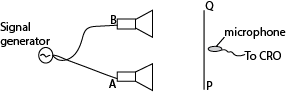
- Two loud speaker A and B were connected to a signal generator.
- A microphone connected to the y-plates of s C.R.O with the time base switched off.
- As the microphone is moved along the line PQ which is parallel to the line joining the loud speaker, the vertical trace on the screen of CRO is seen to increase to maximum and reduce to minimum at equal distances.
- The alternative maximum and minimum intensity are interference pattern.
(b) Using two tubes

Tube A is fixed while B is free to move. A note is sounded at S and detected at E. Tube B s then pulled out slowly. It is noted that the sound detected E increases to a maximum and reduces to minimum intensity at equal intervals of the length of the tube. The alternate maximum and minimum intensity formed are interference pattern.
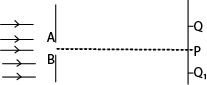
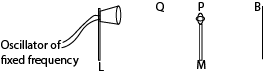
An experiment 1 to determine the velocity of sound in air by an interference method.
Two small loud speakers A and B about 1m apart are connected to the same oscillator so that both emit sound waves of frequency, f, in phase.
A sensitive detector is moved parallel to the line AB along PQ and it detects a maximum wave at P on perpendicular bisector MP of AB and another maximum wave when it first reaches a point Q directly opposite to B.
Constructive interference of sound wave occurs at P and Q, so the wavelength of sound wave is given by λ = AQ –BQ
The speed of sound in air is then calculated from V =fλ.
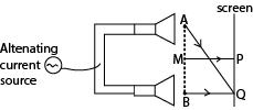
An experiment 2 to determine the velocity of sound in air by an interference method.
- The loud speaker, L is connected to an oscillator of constant frequency, f.
- A microphone, M is connected to the Y-plates of a cathode ray tube.
- The microphone is moved away from B towards L until the amplitude of the wave on C.R.O is maximum.
- The position P of the microphone is noted and distance BP is measured.
- The microphone is move farther away from B to Q where another maximum amplitude of wave front is obtained. Distance BQ is measured and recorded.
- The distance between two successive maxima d= BQ – BP = λ/2 where λ is the wavelength
Velocity of sound = fλ = 2df.
Ultrasonic
Sound waves with frequencies above 20 kHz are called ultrasonic waves. They are emitted by bats. Sound of high frequency that human ear cannot detect is described as ultrasonic.
Applications of ultrasonic sound
Ultrasonic enable bats to judge the distance of an object from the time taken by the reflected wave to return.
Ultrasonic are used in spectacles for blind to judge distances of an object from the time taken by reflected waves to return. Such spectacles contain ultrasonic sender and receiver.
In sonar (echo-sounding system) of ships use ultrasonic wave to measure the depth of sea and to detect shoals of fish.
In industry, ultrasonic waves are used to reveal flaws in welded joints and also holes are cut in glass and steel by ultrasonic drills.
Note:
In an echo sounder (sonar, ultrasonic waves are used because they:-
(i) Cannot be confused with engine sound and other sound made ship,
(ii) Can penetrate sea water to a large distance without undue loss of energy.
(iii) They are not much detracted.
Frequency and audio frequency range.
The human ear has a range of sound frequencies which it can hear. The lowest limit of audibility is about 30Hz and the upper limit audibility for most people is between 20 kHz and 30 kHz.
In daily life, a dog is more able than a human being to detect the presence of a thief tiptoeing at night. A thief tiptoeing at night produces sound of low frequency that can only be detected by dog ears not human being ears because the dog has wider ears than human being ears.
Muscical notes
Musical notes are regular vibrations of sound waves.
Properties of musical notes
Musical notes have three properties namely:
Pitch,
loudness and
quality/timbre
Pitch
A pitch is the sharpness or mildness of the soft musical note. A pitch is directly proportional to the frequency in that high frequency gives high pitch (sharper note).
A high pitched note has high frequency and short wavelength and vice versa.
Loudness and Intensity
This is the amount of sound energy entering the ear per second. The greater the amount of energy, the louder the sound.
The intensity or loudness of sound depends on the amplitude of the vibration in that a loud note has a large amplitude while a quiet note has a small amplitude.
A mother and child may both shout a note of the same frequency but the note from a mother is louder because the amplitude of the sound wave made by the mother is larger so a greater mass of air is set into vibration.
In general, the greater the mass of air which can be set into vibration the louder will be the sound. The prongs of a vibrating tuning fork, make a small mass of air vibrate. So the sound is soft. However if the end of the fork is placed on a table the sound is much louder because a large mass of air in contact with surface of the table is set into vibration.
A violin string directly produces soft sound because very little air is set into vibration as the violin has small surface area.
When the same violin string is attached to a sounding box a much louder sound is produced because the large surface area of the sounding box results in large mass of air to vibrate as the box vibrates,
The sound from a telephone earpiece is heard distinctly only when the ear is placed close to the earpiece because the vibrating circular metal plate inside has a small area so only a small mass of air is set into vibration.
A loud sound may be heard from a small transistor set or a television set because the loud speaker has a vibrating cone with relatively large surface area so a large mass of air in contact is set into vibration.
Intensity of sound
The intensity of sound is the rate of flow of energy per unit area perpendicular to the direction of sound. Intensity is proportional to;
i) The square of the amplitude,
ii) The square of the frequency
iii) The density of the medium
Loudness of sound
Loudness depends on;-
i) The varying pressure exerted on the eardrum by the sound,
ii) The sensitivity of the ear to the different frequencies,
iii) The sound intensity.
Loudness of sound is the sensation of a note in the mind of an individual.
Quality or tone (timbre) of a musical note
The same note on different instruments sounds different, the notes are said to differ in quality or timbre. The difference arises because no instruments except a tuning fork and single generator can emit a pure note i.e. of one frequency but they produced notes consisting of main or fundamental frequency mixed with overtones.
Overtones have frequencies that are exact multiples of the fundamental. The number and strength of overtones determines the quality of a note.
A violin has more and stronger higher overtones than a piano.
Beats
Beats are periodic rise and fall in sound intensity when two sound waves of nearly equal frequency but same amplitude are sounded together.
Rise in sound is due to constructive interference while fall in sound is due to destructive interference.
Conditions for formation of beats
Beats are formed from notes of
nearly equal frequency
same amplitude sounded together
Beat frequency
Is the number of beats formed in one second.
Beat period
Is the time taken to fish one beat after completion of the previous one
Derivation of the expression for beat frequency
Consider two notes of frequencies f1 and f2 sounded together. Suppose the wave of frequency f1 makes one cycle more than that of f2 in time T0.
In time T, the number of waves of f1 is f1T
The number of waves of f2 is f2T
Therefore f1T – f2T = 1
f1- f2 = 1/T
but 1/T=f
∴ f1 –f2 = f, the beat frequency
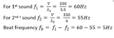
Example 27
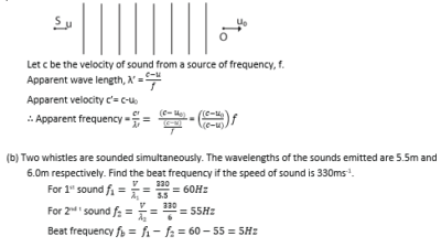
Two whistles are sounded simultaneously. The wavelengths of the sounds emitted are 5.5m and 6.0m respectively. Find the beat frequency if the speed of sound is 330ms-1.
Uses of beats
Tuning a musical instrument to desired note.
Determination of frequency of a musical note.
WAVES IN STRINGS AND PIPES
Vibrating string
Factors on which the frequency of a wave in a vibrating string depend
-Length of the string.
-Tension in the string.
-Mass per unit length of the string.
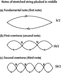
A stationary wave can be set up in a string which has both ends fixed.
The figure below shows the number of waves that can be formed when a string of fixed length is struck in the middle
An experiment to investigate the variation of frequency with length for vibrating wires
A sonometer below is used
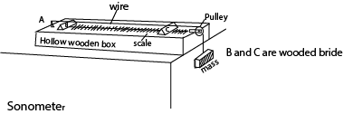
- The wooden bridges B and C vary the effective length of the wire, L.
- Constant tension in the wire is maintained by the fixed mass
- A paper rider is placed on the wire in the middle of BC and a sounding fork placed near it.
- The position of the bridge C is varied until sound is heard.
- The distance between the bridges L and the frequency, f, of the tuning fork is noted.
- The procedure is repeated for various tuning forks and values of L, f and 1/L are tabulated
- A plot of f against 1/L gives a straight line showing that the frequency of vibration of the wire is inversely proportional to length.

An experiment to show the fundamental frequency varies with the tension in a given wire.
A sonometer below is used.
- The length L between the bridges is fixed.
- A suitable mass, m, is attached to the free end of the wire.
- The wire is plucked in the middle and a tuning fork of known frequency, f, is sounded
- The mass m corresponding to the frequency, f, are recorded in the table including values of f2.
- The procedure is repeated for different values of f.
A graph of f2 against m is plotted.

A straight line graph is obtained through the origin, implying that f2 ∝ m
But m = T/g
∴ f = √(T/g) thus increase in tension, T, increases the frequency, f, of the wire.
Example 28
(a) What are overtones?
Overtones are notes of higher frequencies produced by an instrument after fundamental (or main) notes.
(b) Explain why a music tone played on one instrument sound differently from the same note played on another instrument.
When an instrument is played, all the allowed vibration take place producing different frequencies.
The quality of the musical note is determined by the number and strength (intensity) of the overtones.
Thus when the note played on an instrument has fewer overtones, it sounds different from the same note played on different instrument with more overtones.
(c) A stretched string of length L, is fixed at both ends and then set to vibrate in its allowed modes. Derive an expression for frequency of the second overtone in terms of fundamental frequency.
- A stretched string of length L, is fixed at both ends and then set to vibrate in its allowed modes. Derive an expression for frequency of the second overtone in terms of fundamental frequency.

(d) A wire of length 0.60m and mass 9 x 10⁻⁴kg is under tension of 135N. The wire is plucked that it vibrates in its third harmonic. Calculate the frequency of the third harmonic.
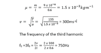
Example 29
A uniform wire of length 1.00m and mass 2.0 x 10⁻²kg is stretched between two fixed points. The tension in the wire is 200N. The wire is plucked in the middle and released. Calculate the
Speed of the transverse waves. (03marks)
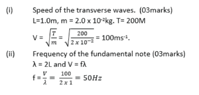
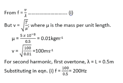
Example 30
A string of length 0.5m and mass 50g is stretched between two fixed points. If the tension in the string is 100N, find the frequency of second harmonic. (04marks)
Resonance
Resonance occurs when a body or system is set into vibrations with its own natural frequency by a nearby body or system vibrating with the same frequency.
The vibrations combine to produce a larger vibration with a larger amplitude.
Thus, resonance occurs when a body is set into vibration with its own natural frequency by another nearby body which vibrates with the same frequency.
Resonance tubes/ vibrating air column /Vibration of air in pipes
In vibrating air column, stationary waves are set up.
There are two types of pipe for air vibration:
(i) Closed pipe
(ii) Open pipe
Resonance in a closed pipe
a) First position of resonance
This occurs when a node is at the closed end and antinodes at the open end
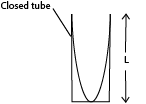
L = λ/4
λ = 4L
The fundamental note f0= V/λ is given out, fo = V/4L
(b) Second resonance
This occurs when a second node is formed such that the length L of vibrating air equals three quarters of a wave length.

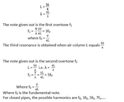
NB: A closed pipe produces only odd notes.
Note:
The frequency of fundamental may alter during the day because this temperature changes of air during the day result in change of velocity of sound.
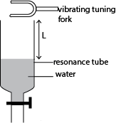
Vibrating turning fork
When the vibrating tuning fork is held over the mouth of tube T, the air inside the tube is set into vibration. The wave sent downwards is reflected from the surface of’ water and a stationary wave is set.
Experiment 1: to determine the speed of sound in air by resonance method- air obtained by raising the tube from water
(a) A tuning fork of known frequency, f, is set into vibration and placed above near the open tube as in the diagram.

The tube is raised from water until the length of air column, L1 is reached when a loud sound is heard. This is the position of first resonance.
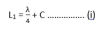
where C is the end correction and λ is the wave length.
While is sounding fork is kept in place; the tube is raised further to length L2 of the air column until a second loud sound is heard. This is the position of the second resonance.
The tube is raised to length L2 and the air column is varied until a loud sound is heard. This is the position of the second resonance.
![]()
where C is the end correction and λ is the wave length.
Subtracting resonance: 2nd position – 1st position

Experiment 2: to determine the speed of sound in air by resonance method- air obtained by draining the tube.
A glass tube which can be drained from bottom is filled with water.
A sounding tuning fork of frequency f is brought to the mouth of the tube.
The water is slowly drained until a loud sound is heard. The tap is closed and length L1 is measured.
The tuning fork is again sounded at the mouth of the tube and the water drained further until a loud sound is heard and distance L2 is noted
Velocity, v, of sound in air = 2f(L2-L1)
Experiment 3: to determine the speed of sound in air using tuning forks of different frequencies and resonate tube.
A resonance tube is place to stand in a tall jar full of water.
Starting with a short length air column, a vibrating tuning fork is held over the mouth of resonance tube. The tube is raised until a point where a loud sound is heard. The length L of the air column and frequency f of tuning fork are recorded.
The experiment is repeated with other five tuning forks of different frequencies
Values of L, f and 1/f are tabulated.
A graph of L against 1/f is plotted and slope S is determined

The velocity, v, of sound = 4S.
The end correction c is an intercept on L axis.
Note that; this experiment shows that frequency is inversely proportional to length of the air column.
The end correction can be obtained.
Note that; this experiment shows that frequency is inversely proportional to length of the air column.
Vibration in open pipes
An open pipe is one which is open at both ends as shown below, Here the antinodes are open at both ends.
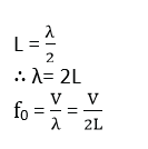
(a) Fundamental note

For fundamental note f0 the air column ‘L’ equals half the wave length.
For 1st overtone f1
For 1st overtone f1 the air column ‘L’ equals the wave length.


For 2nd overtone f2.
For 2nd overtone f2 the air column ‘L’ equals 3/2 the wave length.
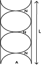
The harmonics present in the open pipe are f0, 2ftf, 3f0, 4f0, …
NB: open pipe produces both odd and even notes.
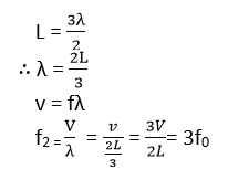
End correction, c
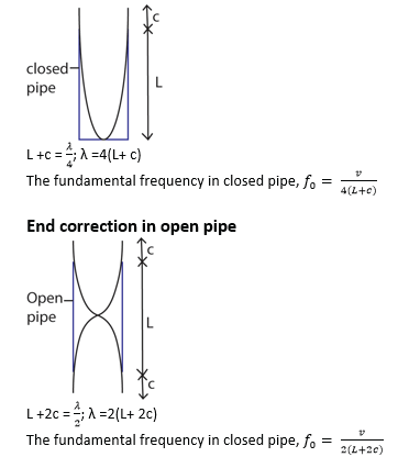
The end correction of an air pipe is a small distance that must be added to actual length of the pipe to account for increase in the effective length of the pipe as a result of the vibrating air column extending beyond the open end of the pipe.
The effective length of the pipe is therefore longer than actual length of the pipe because the vibrating air column extends beyond the open end(s) of the pipe.
The end correction is proportional to the radius of the pipe and the wavelength of sound wave.
Experiment show that end correction, c= 0.6r where r is the radius of the pipe.
End correction in open pipe
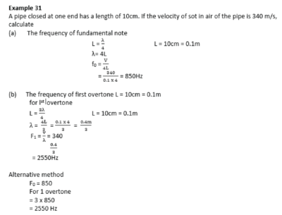
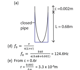
Example 32
A closed pipe of length 0.68m is blown at its open end so that it produced the first harmonic.
(i) Sketch the wave pattern of the pipe
(ii) Determine the frequency of the note produced.
(iii) What is the radius of the pipe?
(End correction of the pipe = 0.002m and velocity of sound is 340m/s)
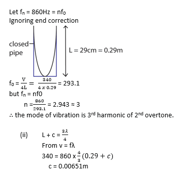
Example 33
A circular pipe of length 29cm is closed at one end. The air in the pipe resonated when a turning fork of frequency 860Hz is sounded. Determine the
(i) Mode of vibration of the pipe
(ii) End correction (the speed of sound in air is 340m/s)
Solution
Advantages of open pipes over closed pipes
Open pipes produce notes of better quality than closed pipes because they produce both odd and even harmonics while closed pipes produce only odd harmonics.
The Doppler Effect
It is the apparent change in frequency of a wave motion due to relative motion between the source and observer.
Calculation of Apparent Frequency based Doppler Effect
Suppose V is the velocity of sound in air, us is the velocity of the source of sound S, u0 is the velocity of an observer 0, and f is the true frequency of the source.
(a) Source moving towards stationary observer.
(i) If the source S were stationary, the f waves sent out in one second towards the observer O would occupy a distance V, and the wavelength would be V/f
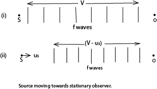
(ii) If S moves with a velocity us towards 0, however, the f waves sent out occupy a distance (V – us), because S has moved a distance us towards 0 in 1s, fig. (ii).

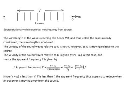
(b) Source moving away from stationary observer.
In this case the f waves sent out towards 0 in 1s occupy a distance (V + us),
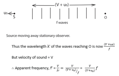
Since (V + us) is greater than V, f’ is less than f; the apparent frequency thus appears to reduce when a source is moving towards an observer.
(c) Source stationary, and observer moving towards it.
Since the source is stationary, the f waves sent out by S towards the moving observer O occupies a distance V,

(d) Source stationary, and observer moving away from it.
Since the source is stationary, the f waves sent out by S towards the moving observer O occupies a distance V,
(e) Source and Observer Both Moving
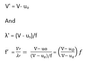
If the source and the observer are both moving, the apparent frequency f’ can be found from the formula f’ = V’/λ’
where V’ is the velocity of the sound waves relative to the observer, and λ’ is the wavelength of the waves reaching the observer. This formula can also be used to find the apparent frequency in any of the cases considered before.
(i) Suppose that the observer has a velocity, uo, the source a velocity us, and that both are moving in the same direction
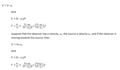
(ii) A source of sound moving with velocity, u. approaches an observer moving with velocity u0 in the same direction. Derive the expression for frequency of sound heard by observer. (05marks)
Example 34
One species of bats locates obstacles by emitting high frequency sound waves and detecting the reflected waves. A bat flying at a steady speed of 5ms-1 emits sound of frequency 78.0 kHz and is reflected back to it.
Derive the equation for the frequency of the sound waves reaching the bat after reflection (05marks)

Example 35
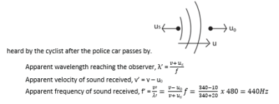
A motor cyclist and police car are approaching each other. The motor cyclist is moving at 10ms-1 and the police car at 20ms-1. If the police siren is sounded at 480Hz. Calculate the frequency of the note heard by the cyclist after the police car passes by.
Example 36
A source of sound moving with velocity, u. approaches an observer moving with velocity u0 in the same direction. Derive the expression for frequency of sound heard by observer. (05marks)
Please download PDF: waves (A-level notes)
Sponsored by The Science Foundation College + 256 753 802709
Shared with a friend
Thank you
Thank you very much
Thank you very much my the almighty God bless you.
I can not stop thanking you great job
Oh thank you so much sir.
What a great compilation of resources on waves. It’s virtually complete for A-level Physics. I greatly appreciate the work you have put on this resources. Thanks Dr. Bbosa
Great contribution
I like ur work
God bless you
This is a must-read for everyone. Thanks! Office Products
I’m always excited to see what’s next. Indian Football
Start your medical journey with MBBS Admission Through Management/Nri Quota in Kerala.
Download now and unlock an amazing gaming experience with the Raja Luck App.